Water Assist Injection Moulded Structural Members

Inactive Publication Date: 2011-12-29
GRGAC STEVEN +3
View PDF16 Cites 11 Cited by
  • Summary
  • Abstract
  • Description
  • Claims
  • Application Information

AI Technical Summary

Benefits of technology

[0011]The present invention provides a method of forming members of fiber reinforced thermoplastic members via molding, the mem

Problems solved by technology

However, generally such single-walled open members or planar members cannot bear structural loads, even when reinforced with glass fibers in the conventional manner.
Accordingly, none of the know

Method used


Image

  • Water Assist Injection Moulded Structural Members
  • Water Assist Injection Moulded Structural Members
  • Water Assist Injection Moulded Structural Members

Examples


Embodiment Construction

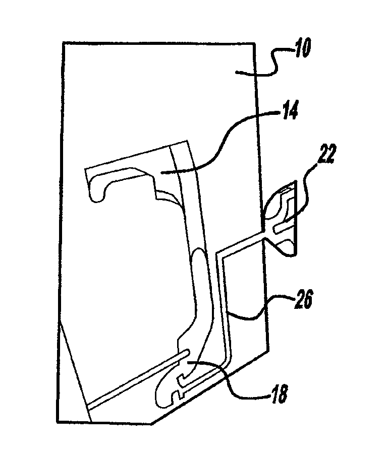
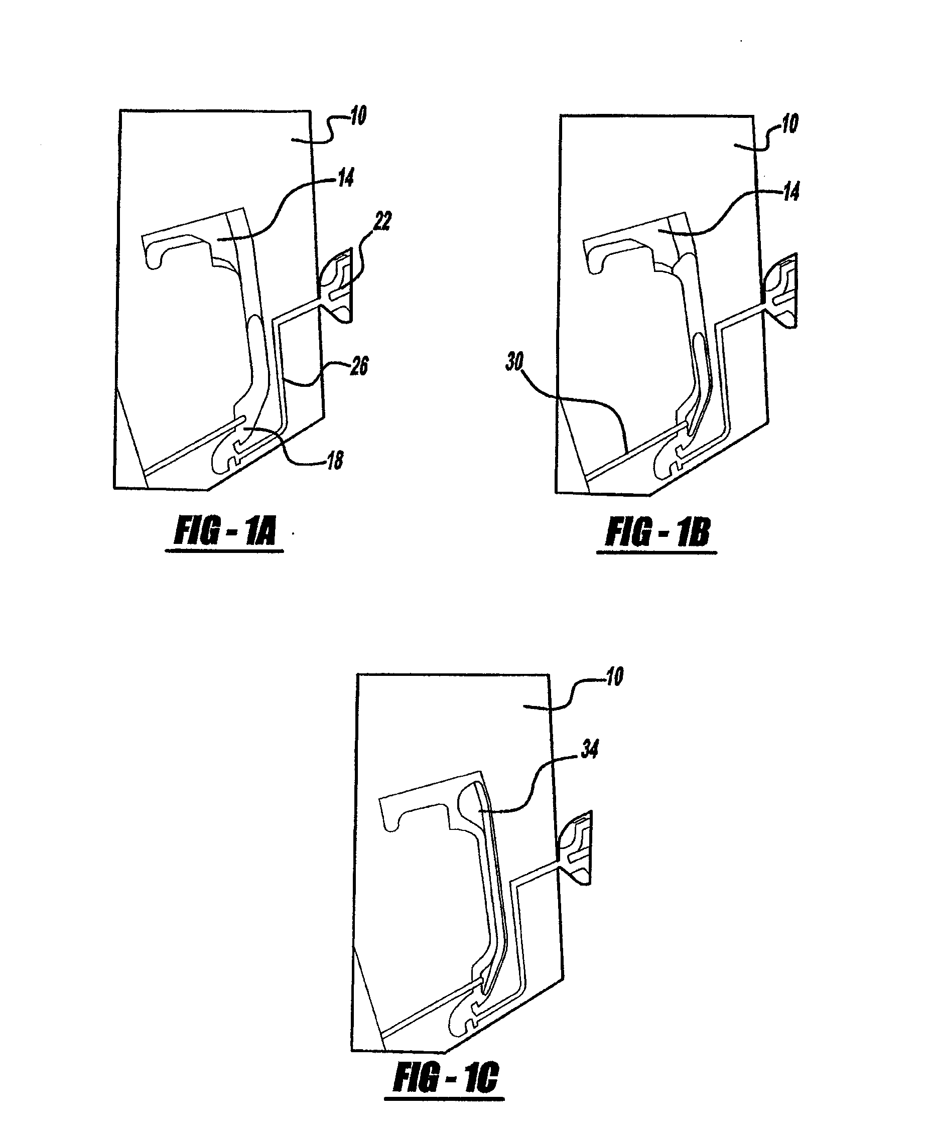
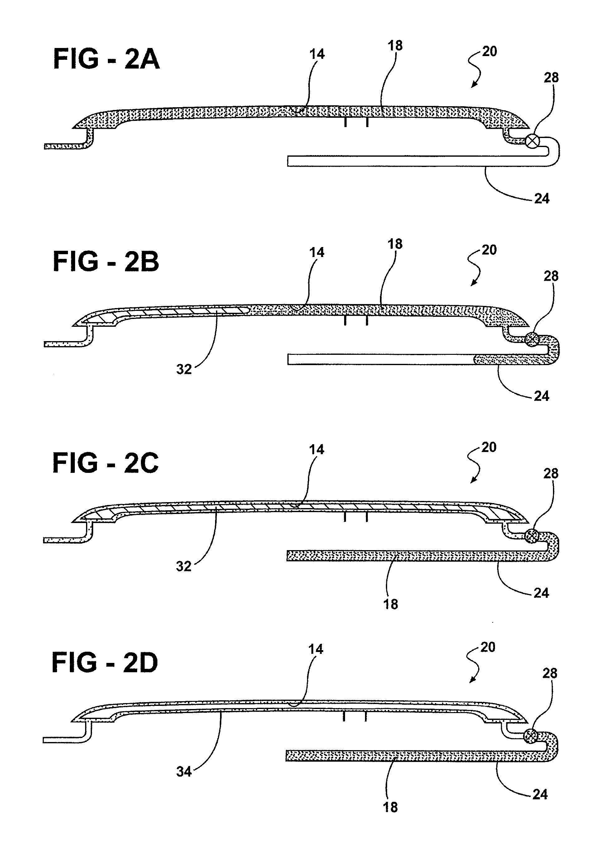
[0015]FIGS. 1a through 1c show a water-assist injection molding process in accordance with the present invention. As shown, a mold 10 includes a cavity 14 for a structural member 34 to be molded. In FIG. 1a, the cavity 14 receives a measured shot 18 of fiber reinforced thermoplastic material, or a full shot of fiber reinforced thermoplastic material. Typically the shot is received from the nozzle 22 of an extruder (not shown) through a runner or feed passage 26. Referring to FIG. 1b, water, or a combination of gas and high pressure water is injected into shot 18 via a water runner 30. The water continues to be injected into shot 18 under pressure, creating a hollow interior cavity in the structural member 34 as shown in FIG. 1c.

[0016]The mold 10 can also be used with an overfill cavity (the overfill method) or without an overfill cavity (the short shot method). Using water or a combination of gas and water provides a number of advantages over strictly gas injection. Water can provi...


PUM

PropertyMeasurementUnit
Lengthaaaaaaaaaa
Lengthaaaaaaaaaa
Fractionaaaaaaaaaa

Abstract

A method of forming members of fiber reinforced thermoplastic members via molding, the members including at least one hollow chamber, formed by water injection into the melt in the mold, to stiffen the finished member. The thermoplastic is preferably selected from a group comprising polypropylene, Nylon, PET, ABS, TPO, and thermoplastic polyurethane, while the reinforcing fibers are preferably selected from a group comprising glass, aramid, carbon, and natural fibers. Preferably, the extruded melt is produced such that the average length of the reinforcing fibers is less than four millimeters.

Description

CROSS-REFERENCE TO RELATED APPLICATIONS[0001]This application claims the benefit of U.S. Provisional Application No. 60 / 840,877 filed Aug. 29, 2006.FIELD OF THE INVENTION[0002]The present invention relates to injection molded members which can be used as structural members in a vehicle body or the like. More specifically, the present invention relates to short glass fiber reinforced thermoplastic members which include hollow chambers formed via water-assist injection molding and can be used as structural members.BACKGROUND OF THE INVENTION[0003]Injection molding of various members used in vehicle bodies and the like is well known. Typically, members are formed from thermoplastic material via injection molding and such members can include single-walled open and / or planar members, such as interior trim pieces, roof rails, etc.[0004]For single-walled open members or planar members which must bear larger loads, such as roof rails, etc., the thermoplastic material is often reinforced wit...

Claims


Application Information

Patent Timeline
IPC IPC(8): B62D25/06B60J9/00B60K37/00B60J5/00B29C45/43B62D25/00
CPCB29C45/0005B29C45/1711B29L2031/3005B29C2045/172B29K2105/12B29C2045/1707
Inventor GRGAC, STEVENLUDWIG, HANS-JOACHIMFISCHER, GERHARDMCLEOD, MARTIN
Owner GRGAC STEVEN
Why Eureka
Try Eureka