Voltage Regulator and Control Circuit and Method Therefor

Active Publication Date: 2011-12-29
RICHTEK TECH
View PDF13 Cites 42 Cited by
  • Summary
  • Abstract
  • Description
  • Claims
  • Application Information

AI Technical Summary

Benefits of technology

[0010]An objective of the present invention is to provide a voltage regulator to improve the response time of the

Problems solved by technology

That is, when the output voltage Vout drops 10 mV, the load current ILOAD increases 10 A. However, the conventional voltage regulator 10 only detects the inductor current IL, but does not detect the actual load current ILOAD Because this requires disposing a power consuming device on the output path.
Consequently, the actual output voltage Vout delays its response to reach a higher level, tha

Method used


Image

  • Voltage Regulator and Control Circuit and Method Therefor
  • Voltage Regulator and Control Circuit and Method Therefor
  • Voltage Regulator and Control Circuit and Method Therefor

Examples


Embodiment Construction

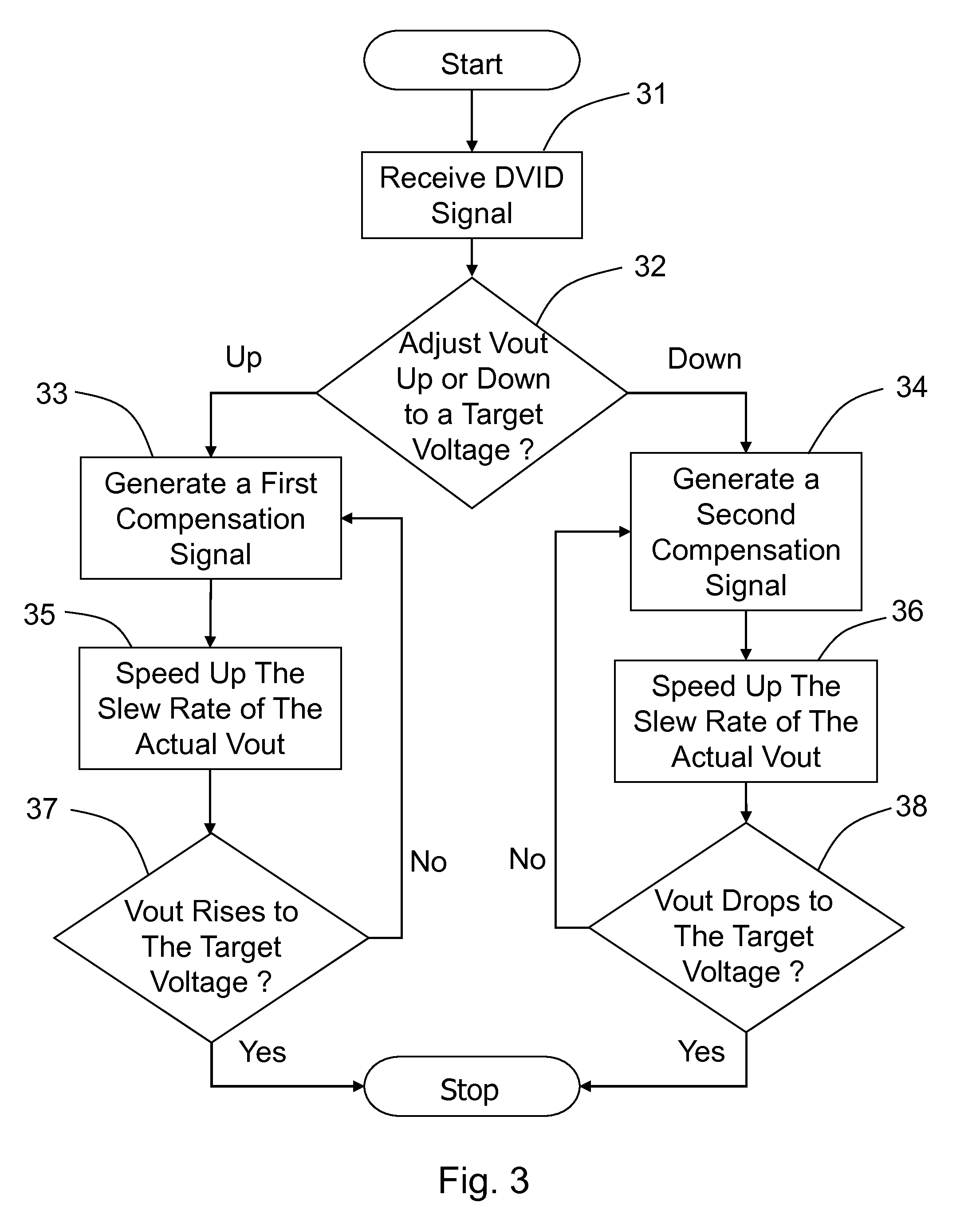
[0040]FIG. 3 shows a flow chart, illustrating the control method of the present invention. As shown in Step 31, a voltage regulator receives a DVID signal from a CPU. The signal instructs the voltage regulator to change its output voltage. The check of Step 32 is executed next. When the signal requests the output voltage to rise to a higher target voltage, the process goes to Step 33; when the signal requests the output voltage to drop to a lower target voltage, the process goes to Step 34. As shown in Steps 33 and 35, the voltage regulator generates a first compensation signal to accelerate the rising speed of the output voltage such that the slew rate of the output voltage approaches the desired slew rate requested by the specification of the DVID signal, and thus shortening an interval for the output voltage to reach the target value. When the output voltage reaches the target value, the process stops in Step 37; otherwise, the process goes back to Step 33.

[0041]As shown in Steps...


PUM


Abstract

The present invention discloses a voltage regulator, and a control circuit and a control method therefor. The method for controlling a voltage regulator comprises: receiving a dynamic voltage identification signal which instructs the voltage regulator to change its output voltage to a target voltage, and generating a compensation signal to shorten an interval for the output voltage of the voltage regulator to reach the target voltage.

Description

CROSS REFERENCE[0001]This application claims the benefit of U.S. Provisional Application No. 61 / 358,592, filed on Jun. 25, 2010.BACKGROUND OF THE INVENTION[0002]1. Field of Invention[0003]The present invention relates to a voltage regulator, and a control circuit and a method for controlling the voltage regulator, in particular to such voltage regulator, control circuit and method wherein a compensation signal is generated to adjust the output voltage of the voltage regulator according to a dynamic voltage identification (DVID) signal.[0004]2. Description of Related Art[0005]The major concept of dynamic voltage adjustment is to supply a variable operation voltage to the system. When the system needs to process data in high speed, the voltage is increased to a higher level to enhance the processing speed of a digital signal processor or a microprocessor. When the system does not need to process data in high speed or it is in a stand-by mode, the voltage is decreased to a lower level ...

Claims


Application Information

Patent Timeline
IPC IPC(8): G05F1/46
CPCH02M3/156Y02B70/16H02M2001/0032H02M1/0032Y02B70/10
Inventor FENG, CHIEH-MINWANG, TING-HUNGCHENG, CHUNG-SHENGHUANG, JIAN-RONG
Owner RICHTEK TECH
Why Eureka
Try Eureka