Eureka AIR delivers breakthrough ideas for toughest innovation challenges, trusted by R&D personnel around the world.

Power transmission monitoring and maintenance systems and methods

a technology for monitoring and maintenance systems and power transmission systems, applied in the direction of machine parts testing, structural/machine measurement, instruments, etc., can solve the problems of system shock load, belts may have a shorter life span, power transmission systems may lose efficiency,

Active Publication Date: 2011-12-29
SCHRADER ELECTRONICS LTD
View PDF22 Cites 17 Cited by
  • Summary
  • Abstract
  • Description
  • Claims
  • Application Information

AI Technical Summary

Benefits of technology

[0007]The present invention is directed to systems and methods which provide power transmission system monitoring and maintenance. “Slip,” as discussed herein may mean slip of a belt in a non-synchronous power transmission system, or in accordance with some embodiments skip of one or more teeth in a synchronous power transmission system, in that one pulley in the power transmission system rotates faster, or slower, than another pulley in the system, due to drag, obstruction, bearing wear, misalignment, incorrect belt tension, or the like, acting on the slower pulley, or the like. The pr...

Problems solved by technology

When a power transmission belt slip or skips the belt may overheat; the surface of the belt may become smooth and shiny, losing friction; bearings in the power transmission system may be shock loaded; the power transmission system loses efficiency; the belt may have a shorter life span; and / or system downtime may increase.
In both cases embedding such sensors is expensive and requires special production methods and additional materials which are extraordinary to the normal use of the belt.

Method used


Image

  • Power transmission monitoring and maintenance systems and methods
  • Power transmission monitoring and maintenance systems and methods
  • Power transmission monitoring and maintenance systems and methods

Examples


Embodiment Construction

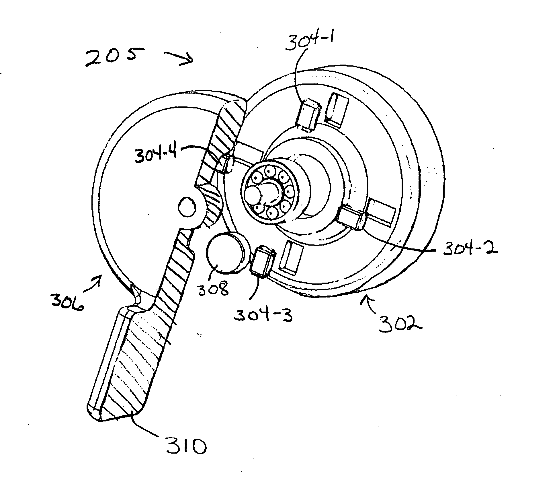
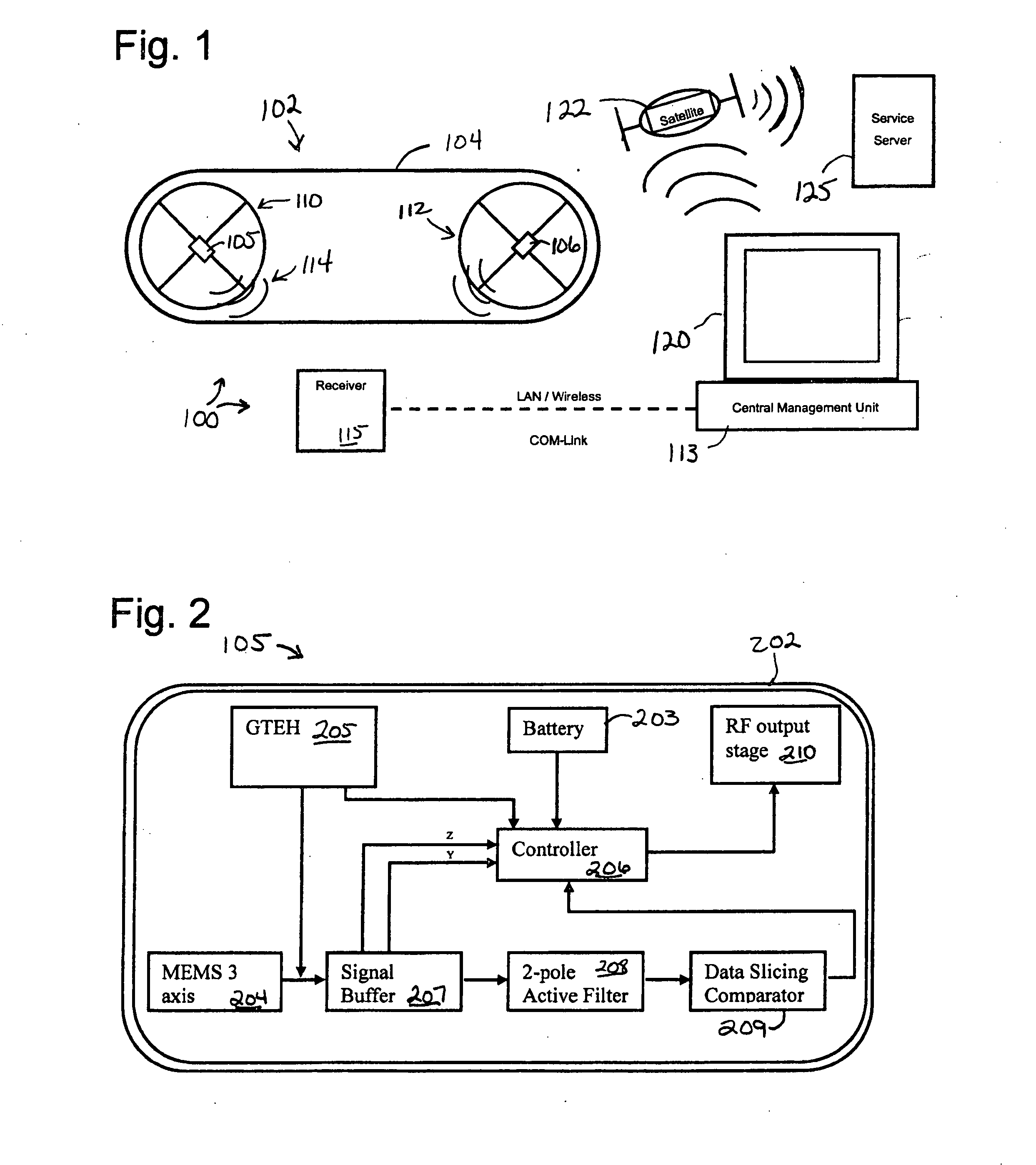
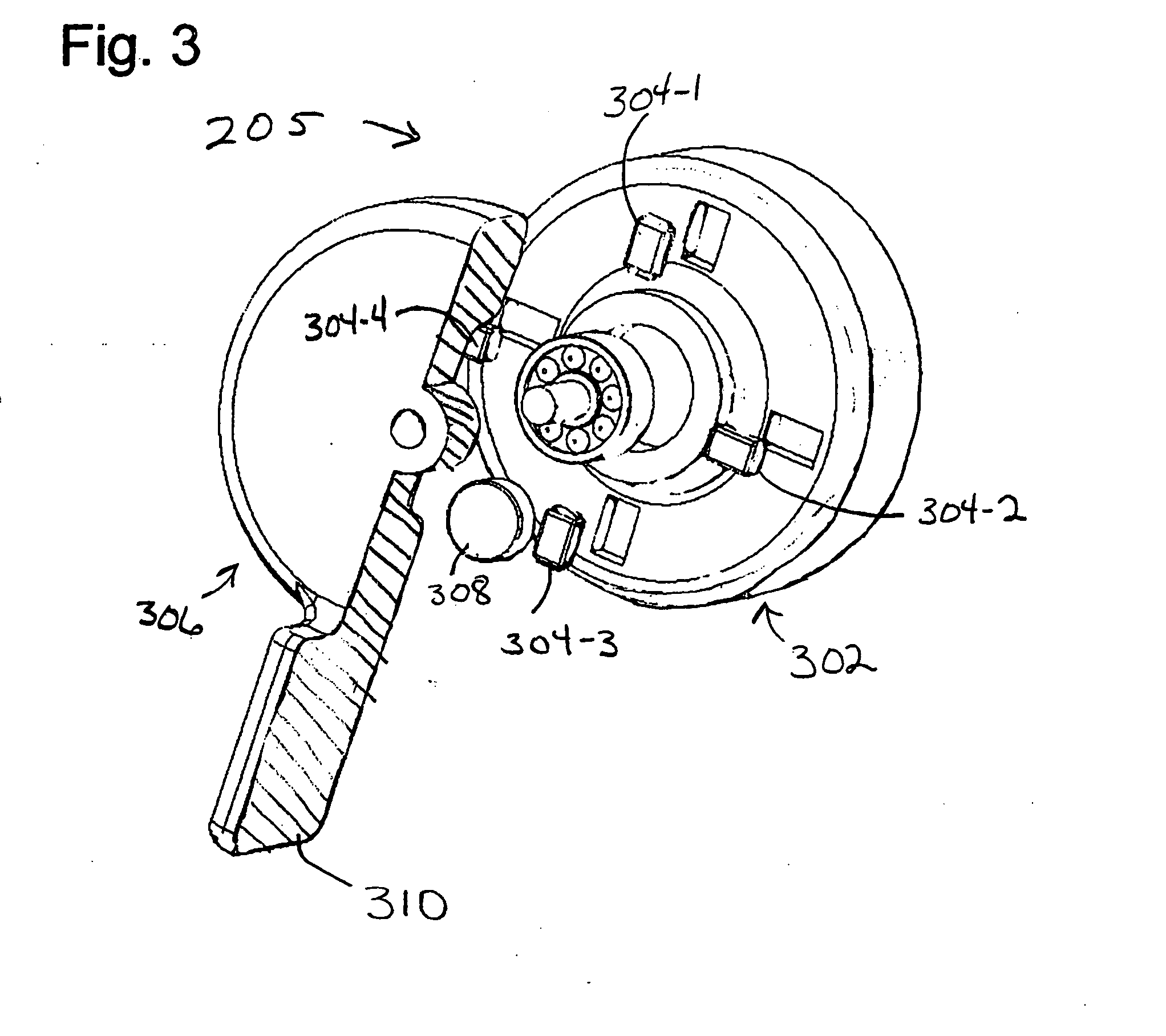
[0018]The present systems and methods monitor various failure modes in rotational drive systems that may or may not be belt driven. While the present systems and methods are described herein with respect to slip, it should be appreciated that the present systems and methods can be used to monitor any number of rotational drive systems and related failure modes. FIG. 1 is a diagrammatic environmental view of power transmission system 102 employing an embodiment of present system 100 for determining slip in power transmission system 102. Sensing technologies embodied in system 100 might be expressly aimed at the industrial and manufacturing sector with a view to providing life data for consumable or wearing parts such a power transmission belts (104) or pulley bearings. However, the present systems and methods are also well adapted for use in automotive and / or mobile equipment power transmission systems as well. Real-time analysis of wearing parts offers a balance between part life an...


PUM


Abstract

Power transmission monitoring systems includes rotation speed sensors mounted to hubs of a power transmission pulley. A sensor comprises a rotation sensing device, and a controller receiving rotation data therefrom and determining rotation speed of the pulley. A transmitter transmits rotational speed of the pulley to a receiver, which may include or be connected to a device that compares the rotational speed to rotational speed in transmissions from other sensors to determine slip in the power transmission system. The rotation speed sensing device may be an accelerometer, or a gravitational torque harvester. A harvester might include a rotor body rotating with the pulley and mounting induction coils, and a gravitational torque stator mounting an induction magnet and including an air vane damper maintaining the stator stationary with respect to the rotor, through air resistance. The transmissions may be employed to monitor, maintain and repair the power transmissions system.

Description

BACKGROUND[0001]1. Field of the Invention[0002]This invention relates generally to power transmission systems, more particularly monitoring and maintenance of power transmission systems, and specifically to monitoring of slip and the like of power transmission drives, such as belts, and other conditions, such as vibration in power transmission systems.[0003]2. Description of the Prior Art[0004]When a power transmission belt slip or skips the belt may overheat; the surface of the belt may become smooth and shiny, losing friction; bearings in the power transmission system may be shock loaded; the power transmission system loses efficiency; the belt may have a shorter life span; and / or system downtime may increase.[0005]Traditionally the majority of industrial power transmission belt changes are carried out on a runtime or time interval basis. This is known as “Scheduled Preventative Maintenance.” Such planned maintenance and regular belt tension checks, direct slip measurement using c...

Claims


Application Information

Patent Timeline
IPC IPC(8): G01P3/42
CPCG01M13/023
Inventor LYNN, WILLIAM DAVID
Owner SCHRADER ELECTRONICS LTD
Why Eureka
Eureka Blog
Learn More