Monolithic optical mount

a monolithic and optical mount technology, applied in the field of monolithic optical mounts, can solve the problems of increased production costs, increased production costs, and increased deformations of the inner parts, and achieves the effects of shortening the hinged brackets, reducing production costs, and increasing lateral stiffness

Inactive Publication Date: 2011-12-29
JENOPTIK OPTICAL SYST
View PDF5 Cites 2 Cited by
  • Summary
  • Abstract
  • Description
  • Claims
  • Application Information

AI Technical Summary

Benefits of technology

[0014]As explained in EP 1 577 693 A2, during the heating of the optical clement, e.g., a lens, the problem arises that the it is difficult for heat to dissipate via the few and narrow connection points between the inner ring and the outer mount. The temperature differences developing thereby have disadvantageous effects upon the imaging quality, because particularly a longitudinal change of the hinged brackets extending in the same direction leads to a displacement of the inner ring in said direction due to temperature changes, which results in aberrations and coma.
[0015]This problem is attained in a lens mount according to EP 1 577 693 A2 essentially such that the hinged brackets engage, off-set in reference to each other in the tangential direction by 120°, at the outer circumferential area of the inner ring and at the inner circumferential area of the outer mount in the clock-wise direction away from the inner ring. A longitudinal change of the hinged brackets is here converted into a uniform direction of distortion. Distortions of this kind lead not to any aberrations, particularly not if lenses are the optical elements.
[0016]A lens mount according to EP 1 577 693 A2 is also said to be advantageous in that a higher lateral stiffness of the inner ring connection can be achieved by shortening the hinged brackets and thus the lens mount with the mounted lens is stiffer in reference to internal oscillations. A higher lateral stiffness by shortening the hinged brackets is achieved at the expense of the sensitivity of the adjustment, which not only concerns the length of the members but also the extend of the hinged brackets bending.
[0017]The length of the hinged brackets is here still predetermined by the tolerable material stress. This means when in a predetermined adjustment path and predetermined sensitivity the tolerable material stress limit is reached -hen no further shortening of the joints is possible to increase stiffness and / or resonance frequency. Consequently, always two relatively thin and, compared to the cross-section relatively tong hinged brackets are necessary to implement the function as an adjustment unit and / or joint, which generally restricts the lateral and axial stillness achievable.
[0018]In DE 10 2007 030 579 A1, a first embodiment for a laterally adjustable lens mount is described, in which it is essentially equivalent to one according to EP 1 577 693 A2, i.e., three manipulator units arranged off-set by 120° in reference to each other are each embodied as members, which at their stationary ends transfer into two tangentially aligned hinged brackets, here called bars, which are connected to the inner mount part and / or the outer mount part.
[0019]In second embodiment the bars connecting the member to the inner and / or outer mount part are aligned radially, thus achieving higher lateral stiffness.

Problems solved by technology

The disadvantage of this solution particularly comprises that it shows a complicated and asymmetrical design due to a plurality of differently shaped manipulator units, here called manipulator elements, which is unsuitable for symmetric systems or leads to system instabilities.
In particular, the connecting members, acting as reinforcements in the direction of the optical axis but unnecessary cinematically, increase the production expenses, require additional actuators depending on their number, and cause deformations having a greater effect upon the inner part.
Using a lens mount decoupled from deformations, no adjustment of any lens held in the inner mount ring is possible in reference to the outer mount ring, thus it cannot relate to a mount for a radial adjustment of a mounted lens.
This lens mount can compensate for differences in the expansion of the lens and the lens mounting due to fluctuating temperatures, however a mounted lens cannot be adjusted radially.
As explained in EP 1 577 693 A2, during the heating of the optical clement, e.g., a lens, the problem arises that the it is difficult for heat to dissipate via the few and narrow connection points between the inner ring and the outer mount.
The temperature differences developing thereby have disadvantageous effects upon the imaging quality, because particularly a longitudinal change of the hinged brackets extending in the same direction leads to a displacement of the inner ring in said direction due to temperature changes, which results in aberrations and coma.
The development of undesired tensions in the inner ring is unavoidable here.
In order to yield high sensitivity with an appropriate adjustment travel the bars and / or hinged brackets are embodied tong, which may lead to distortions in the axial direction.
The highly precise production of such mounts as well as the sensitive adjustability of an optical element in this mount is particularly opposed by high production costs due to the use of electro-erosive methods, which then seem unjustified if there are no higher requirements on the precision for the adjustment of such an optical element held in the mount.

Method used


Image

  • Monolithic optical mount
  • Monolithic optical mount
  • Monolithic optical mount

Examples


Embodiment Construction

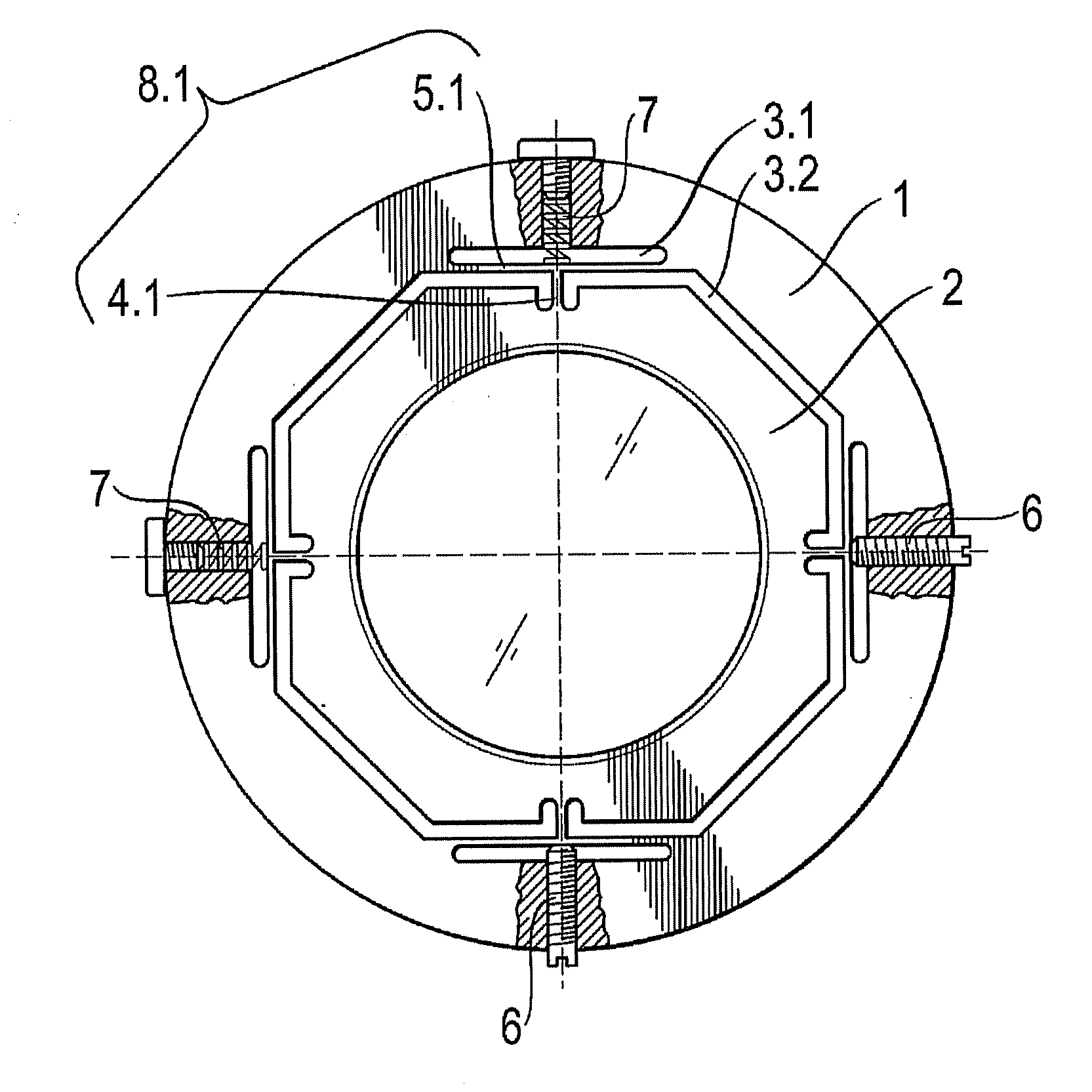
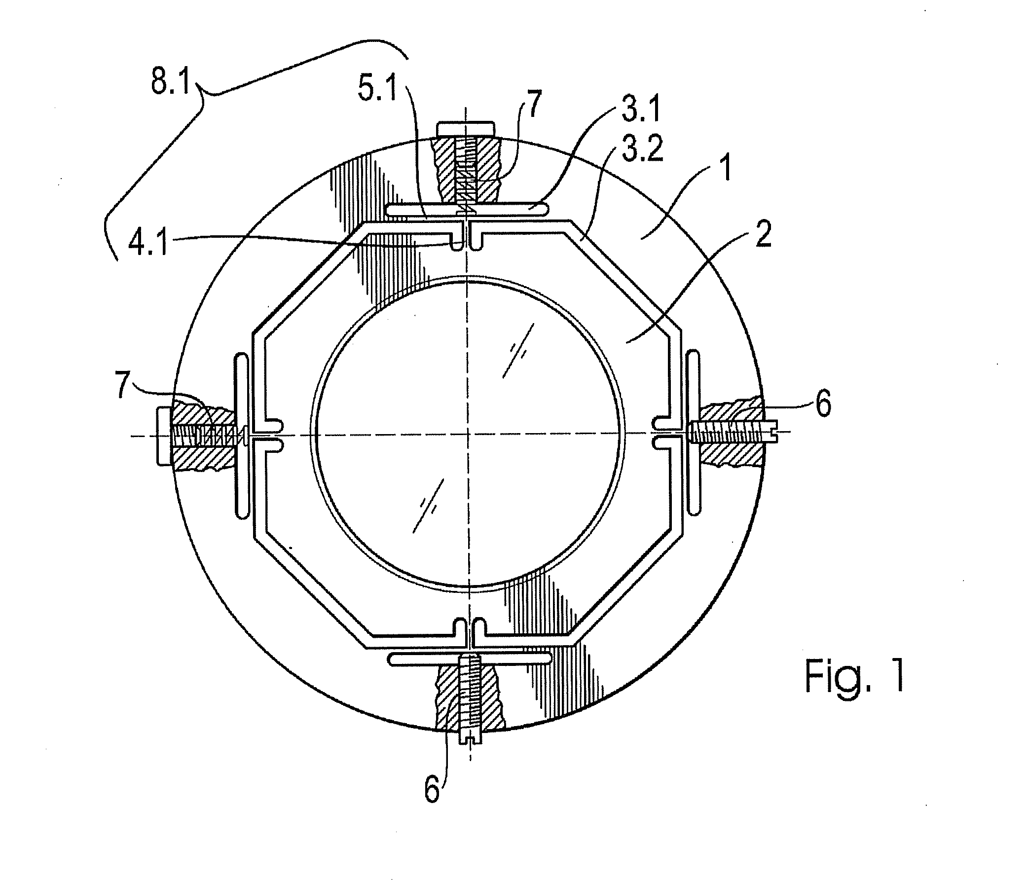
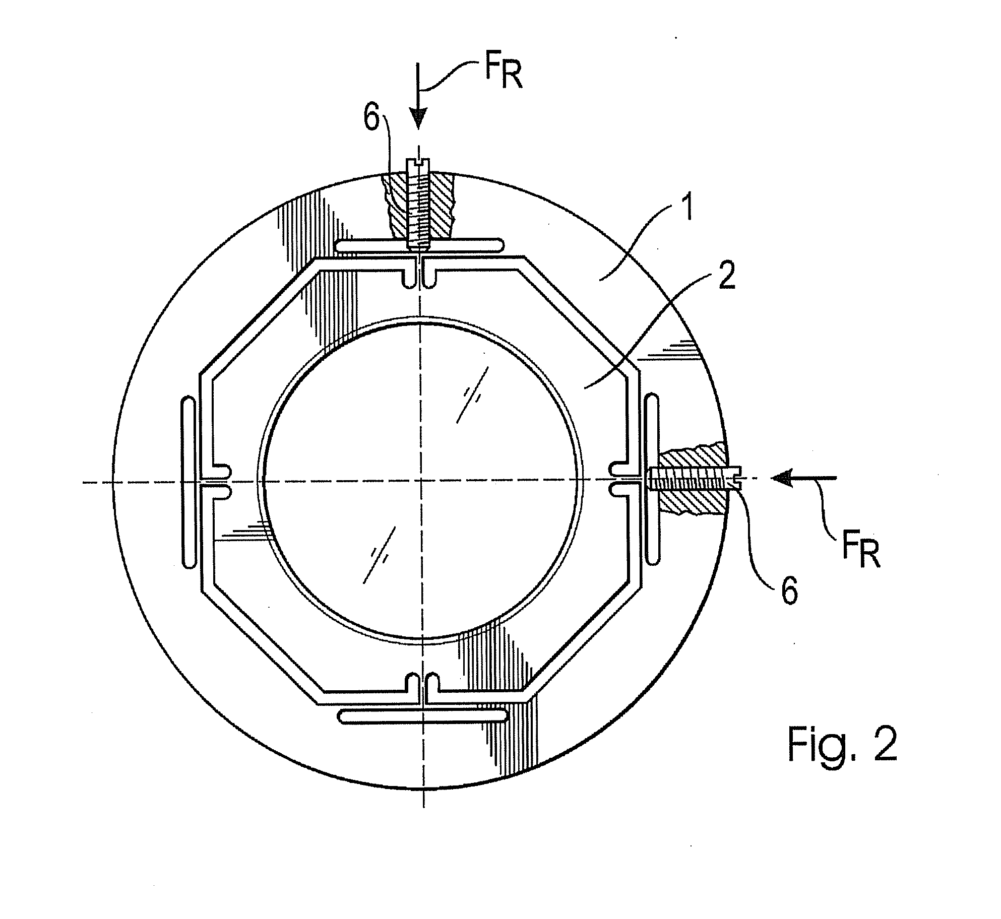
[0036]The embodiments shown in FIGS. 1 through 4 of a monolithic optical mount according to the invention are optical mounts with lens mounts. Similar to mounts known in prior art from DE 10 2007 030 579 A1 are made from a rotary-symmetrical planar body, particularly comprising steel, aluminum, or brass and are divided by several cutouts 3 into a stationary outer mount ring 1 and a laterally adjustable inner mount ring 2.

[0037]In general, using an optical mount according to the invention other optical elements, such as mirrors or beam splitters, may also be mounted. In general, they are not subject to such precise adjustment requirements, thus the mount is particularly useful for lens mounts.

[0038]Also similar to the lens mount according to DE 10 2007 030 579 A1, in a mount according to the invention uniform manipulator units are formed by the cutouts 3, equally off-set in reference to each other, by which at a certain introduction of a radially acting force FR a displacement of the...


PUM


Abstract

The invention relates to a monolithic optical mount, which is divided by a plurality of cutouts into a stationary outer mount ring, a laterally adjustable inner mount ring, and manipulator units that are arranged with uniform offset from each other and formed by the remaining material connections. The cutouts have a uniform constant width and can therefore advantageously be produced by milling. The manipulator units have a simple geometrical design in the form of T- or L-shaped webs.

Description

RELATED APPLICATIONS[0001]The present application is a U.S. National Stage application of International PCT Application No. PCT / DE2009 / 050070 filed on Dec. 9, 2009 which claims priority benefit of German Application No. DE 10 2008 063 223.6 filed on Dec. 23, 2008, the contents of which are incorporated herein by reference in their entirety.FIELD OF THE INVENTION[0002]The invention relates to a monolithic optical mount, particularly a lens mount, which is divided by cutouts into a stationary outer mount ring and a lateral inner mount ring, adjustable in the vertical direction in reference to the optical axis of a mounted optical clement. Such mounts allow for a radial adjustment of on optical element mounted in the inner mount ring in reference to the stationary outer mount ring, which is generally connected stationary to a housing and / or mounts of other optical elements. A generic mount is known from DE 10 2007 030 579 A1.BACKGROUND OF THE INVENTION[0003]An optical imaging device is...

Claims


Application Information

Patent Timeline
Patent Type & Authority Applications(United States)
IPC IPC(8): G02B7/02
CPCG02B7/004
Inventor BORNSCHEIN, MARCO
Owner JENOPTIK OPTICAL SYST
Why Eureka
Try Eureka