Modular electrical card for power components

a technology of power components and modules, applied in the direction of printed circuit board receptacles, electrical apparatus construction details, electrical apparatus casings/cabinets/drawers, etc., can solve the problems of poor heat diffusion, temperature inside an electrical card can reach critical values, and the current conveyed in power modules may reach large magnitudes. , to achieve the effect of improving cooling

Active Publication Date: 2011-12-29
SAFRAN ELECTRONICS & DEFENSE
View PDF1 Cites 2 Cited by
  • Summary
  • Abstract
  • Description
  • Claims
  • Application Information

AI Technical Summary

Benefits of technology

[0007]Thus, maintenance of the electrical card containing power components is made easier and the electrical ground plate acts as a heatsink. Because of its large dimensions, it serves to diffuse heat quickly.
[0009]The metal reinforcement plate also acts as a heatsink and it possesses large dimensions that enable it to diffuse heat quickly.
[0011]Thus, the ground plate serves not only to diffuse the heat generated by the power components, but it also provides thermal and electromagnetic protection to the connection buses and to the associated control components.
[0012]According to other advantageous characteristics of the invention, the power components are carried by power strips extending perpendicularly to the electrical ground plate and arranged so as to co-operate with the electrical ground plate to define elongate channels, the control components are carried by strips extending in the channels, being spaced apart from the power strips, and preferably the control components are carried by control strips extending in an axial direction of the channels halfway between the ends of the channels. Thus, the control components are located in the middles of the air streams flowing in the channels, thereby minimizing the heating that results from heat being transmitted from the power components by conduction or by radiation.

Problems solved by technology

Nevertheless, the currents that are conveyed in power modules may reach large magnitudes, for example several tens of amps.
Such currents heat the conductors, and present devices provide poor diffusion of heat, such that the temperature inside an electrical card can reach critical values, in particular when the electrical card is mounted in an airplane that is designed to fly at high altitudes where the air is rarefied, or indeed in the event of a failure of a fan device in the electrical unit that supports the electrical card.

Method used


Image

  • Modular electrical card for power components
  • Modular electrical card for power components
  • Modular electrical card for power components

Examples


Embodiment Construction

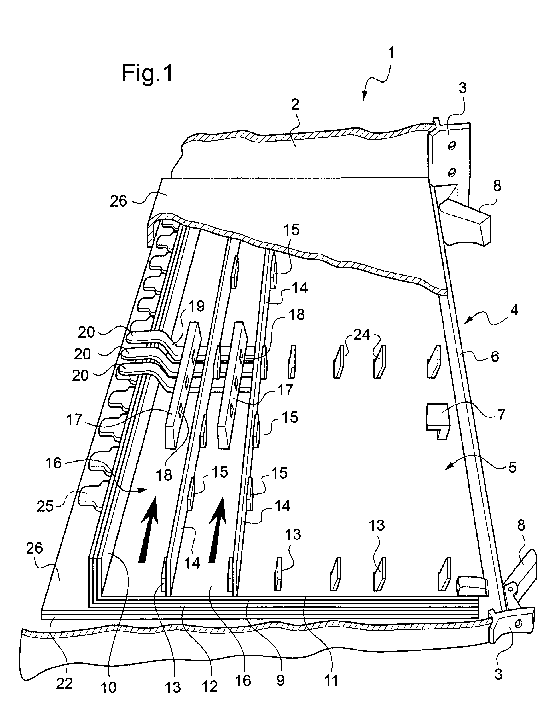
[0016]With reference to FIG. 1, the electrical unit given overall reference 1 comprises an outer casing 2 having support rails 3 fastened therein, with cards 4 fixed to the rails, only one card being shown in figures.

[0017]In the embodiment shown, the unit is drawn lying on one side. Each card 4 comprises a support plate 5 that, when in the mounted position, extends vertically inside the unit. On its edge corresponding to the support rail 3, each card is fitted with a front wall 6 that is fastened to the support plate 5 perpendicularly thereto by assembly blocks 7 and that is fitted with locking members 8 that co-operate with the support rails 3.

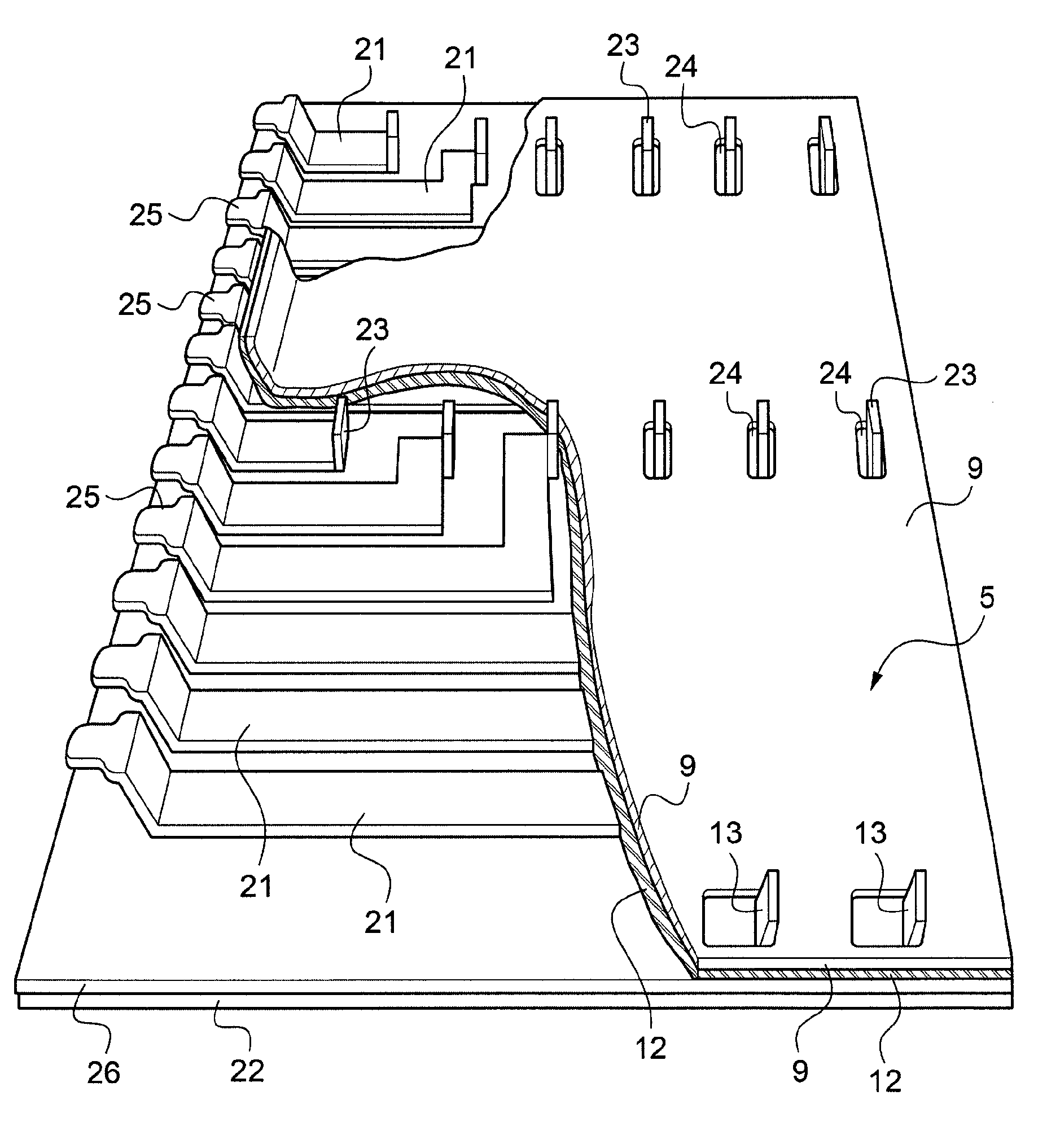
[0018]The support plate 5 comprises a metal electrical ground plate 9 that can be seen more clearly in FIG. 2, on which component strips and connection buses connecting with the control components are shown separated, and that is partially cut away in order to show more clearly the structure of the power buses. Along its rear edge, the elect...


PUM


Abstract

The electrical card has power modules constituted by power components and by control components that are carried by strips fastened on a support plate comprising an electrical ground plate. The power components are connected firstly to control buses, and secondly to power buses carried by the support plate and extending in a layer adjacent to the electrical ground plate.

Description

[0001]The present invention relates to a modular electrical card, and more particularly, but not exclusively, to a circuit breaker module card.BACKGROUND OF THE INVENTION[0002]Given the increasing use of electrical controls in vehicles, whether land vehicles or aircraft, it is now common practice to fit such vehicles with electrical units that contain electrical cards including power components. In order to facilitate the maintenance of an electrical unit, functions are generally performed by components that are grouped together in power modules, each of which comprises power components and control components.[0003]In existing cards, power buses are generally made in the form of multi-layer circuits, each module being powered by a conductor plane that is made from a single layer. That configuration makes it possible to adapt the layout of the power supply planes to the arrangement of the power components on the card.[0004]Nevertheless, the currents that are conveyed in power modules...

Claims


Application Information

Patent Timeline
Patent Type & Authority Applications(United States)
IPC IPC(8): H05K7/14
CPCH05K1/0263H05K2201/10272H05K7/1461H05K7/1432H05K7/1457H05K7/14325
Inventor MERLET, ETIENNEBESOLD, JEAN-ERIC
Owner SAFRAN ELECTRONICS & DEFENSE
Why Eureka
Try Eureka