Process cartridge

Active Publication Date: 2011-12-29
CANON KK
View PDF5 Cites 13 Cited by
  • Summary
  • Abstract
  • Description
  • Claims
  • Application Information

AI Technical Summary

Benefits of technology

[0013]A principal object of the present invention is to provide a process cartridge, in which an image bearing member and a developing device are integrally assemb

Problems solved by technology

With respect to the developing device or process cartridge in which the developer carrying member and the developer stirring (feeding) member are integrally interrelated with each other by the gear mechanism, vibration generated by the gear mechanism with an operation of the developing device is problematic.
Vibration of various frequency components generated by variation in engagement of the gear mechanism produces resonance to vibrate the image bearing member, so that pitch non-uniformity of image scanning lines occur.
This is problematic and therefore a structure for dampering the vibration is incorporated in the gear mechanism.
Further, when the vibration of the developing device is transmitted to a casing structure of the image forming apparatus, the vibration is transmitted to a laser beam exposure device through the casing structure, so that the pitch non-uniformity of the scanning lines which is amplified to several tens of times through an optical system.
However, in the constitutions of JP-A Hei 06-051576 and JP-A Hei 10-171331, the vibration generated from the gear mechanism itself is transmitted to a frame as it is, so that the pitch non-uniformity of the image scanning lines occurs.
However, in the case of a cartridge detachably

Method used


Image

  • Process cartridge
  • Process cartridge
  • Process cartridge

Examples


embodiment 1

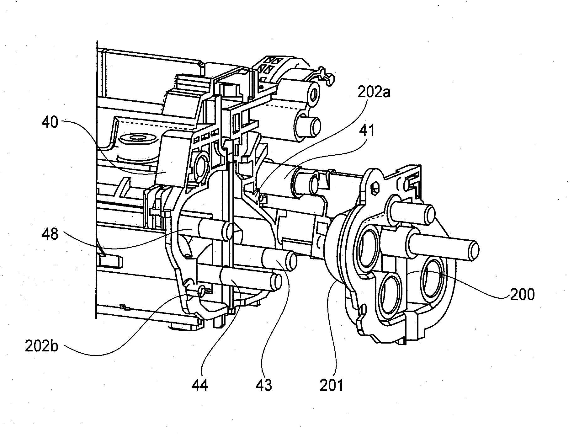
[0065]Parts (a) and (b) of FIG. 5 are illustrations of a side member in this embodiment. FIG. 6 is an illustration of an assembling structure of the side member in this embodiment. FIG. 7 is an illustration of a gear structure. FIG. 8 is an illustration of a mounted structure of a front cover.

[0066]As shown in FIG. 5 with reference to FIG. 3, the gear mechanism 30 as a develop connection means in this embodiment interrelate the rotates of the developing sleeve 41 and the developer stirring members 43 and 44 at the outside of the developing container 40 with respect to the longitudinal direction. A side member 200 which is an example of the supporting member is supported by the developing container 40 via an elastic member 201 which is an example of a vibration damping member having a vibration transmission performance lower than that of the developing container 40. The side member 200 integrally supports the developing sleeve 41, the developing screw 43, the stirring screw 44 and th...

embodiment 2

[0086]FIG. 9 is an illustration of a planar structure of a developing device in this embodiment. Parts (a) and (b) of FIG. 10 are illustrations of a side member in this embodiment. FIG. 11 is an illustration of an assembling structure of the side member in this embodiment. FIG. 12 is an illustration of a planar arrangement of a gear structure.

[0087]As shown in FIG. 9, in this embodiment, compared with Embodiment 1, the side member is formed in a large size, so that the developing sleeve 41 and the photosensitive drum 1a are also integrally supported by the side member. With respect to the developing container 40 and the respective rotatable members, the same constitutions as those in Embodiment 1. Therefore, in FIGS. 9 to 12, constituent elements common to Embodiment 1 are represented by the same reference numerals or symbols and are omitted from redundant description.

[0088]As shown in (a) of FIG. 10, an elastic member 204 is mounted to a side member 203. The elastic member 204 is p...


PUM


Abstract

A process cartridge detachably mountable to a main assembly of an image forming apparatus includes an image bearing member; a developer carrying member for developing an electrostatic image on the image bearing member; a first gear provided on the developer carrying member and a second gear driving-connected to the first gear; and a supporting portion for rotatably supporting the second gear. The supporting member is mounted on a frame of the process cartridge through a vibration damping member having a vibration transmission performance lower than that of at least the supporting portion.

Description

FIELD OF THE INVENTION AND RELATED ART[0001]The present invention relates to a process cartridge including a developing device in which a developer carrying member and a developer stirring member are interrelated with a gear mechanism provided at a longitudinal end portion. Specifically, the present invention relates to a structure for damping vibration of an image bearing member due to vibration generated by the gear mechanism.[0002]An image forming apparatus in which an electrostatic image formed on the image bearing member is developed into a toner image and the toner image is transferred onto a recording material directly or via an intermediary transfer member and then is heat-fixed has been widely used.[0003]In the developing device, the developer carrying member (developing sleeve or developing roller) and a plurality of developer stirring members (feeding screw and stirring blade) and disposed side by said with respect to a longitudinal direction. These members are connected ...

Claims


Application Information

Patent Timeline
IPC IPC(8): G03G21/18
CPCG03G21/1842G03G2221/1648G03G21/1857G03G15/0881
Inventor SHIRAYANAGI, JUN
Owner CANON KK
Why Eureka
Try Eureka