Ultrasonic photoacoustic imaging apparatus and operation method of the same

a photoacoustic imaging and ultrasonic technology, applied in ultrasonic/sonic/infrasonic diagnostics, medical science, diagnostics, etc., can solve problems such as difficult determination, and achieve the effect of decreasing signal strength and decreasing signal strength

Inactive Publication Date: 2011-12-29
FUJIFILM CORP
View PDF0 Cites 67 Cited by
  • Summary
  • Abstract
  • Description
  • Claims
  • Application Information

AI Technical Summary

Benefits of technology

[0025]Preferably, the acoustic image generation unit is a unit that generates the electrical signal reflecting the ultrasonic wave by performing a first threshold process on an electrical signal generated by the first addition process for decreasing signal strength less than a predetermined threshold value and generates the electrical signal reflecting the photoacoustic wave by performing a second threshold process on an electrical signal generated by the second addition process for decreasing signal strength less than a predetermined threshold value.
[0026]Further, it is preferable that the ultrasonic wave projection unit is a unit that projects a collimated ultrasonic wave. In this case, it is preferable that the ultrasonic photoacoustic imaging apparatus further includes a timing control unit for performing control such that projection timing of the collimated ultrasonic wave and projection timing of the light are synchronized.

Problems solved by technology

The reason for this is that the ultrasonic wave and photoacoustic wave are identical in that they are acoustic waves propagating in the inside of a subject and this causes a problem that, when an acoustic wave is detected by a detector (probe or the like), it is simply difficult to determine whether the detected acoustic wave is an ultrasonic wave or a photoacoustic wave, or a problem that, when an ultrasonic wave and a photoacoustic wave are detected simultaneously by the same detector, these waves are detected as a superimposed single acoustic wave.
The method described in Japanese Unexamined Patent Publication No. 2005-021380, however, is only applicable to a case in which the ultrasonic wave and photoacoustic wave have different frequencies and they are detected by different detectors, thereby requiring a special detector, such as a two-frequency probe or the like.

Method used


Image

  • Ultrasonic photoacoustic imaging apparatus and operation method of the same
  • Ultrasonic photoacoustic imaging apparatus and operation method of the same
  • Ultrasonic photoacoustic imaging apparatus and operation method of the same

Examples


first embodiment

of Ultrasonic Photoacoustic Imaging Apparatus and Operation Method of the Same

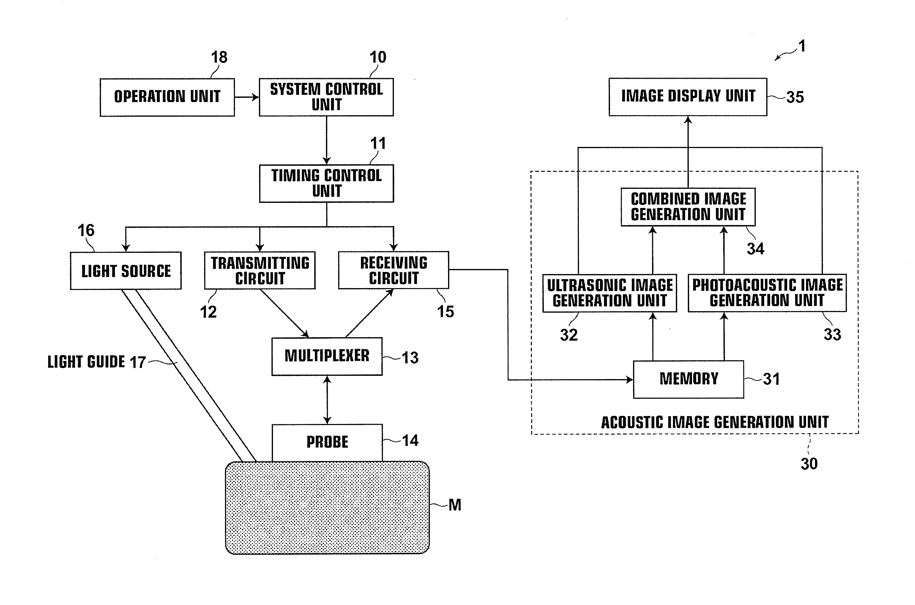
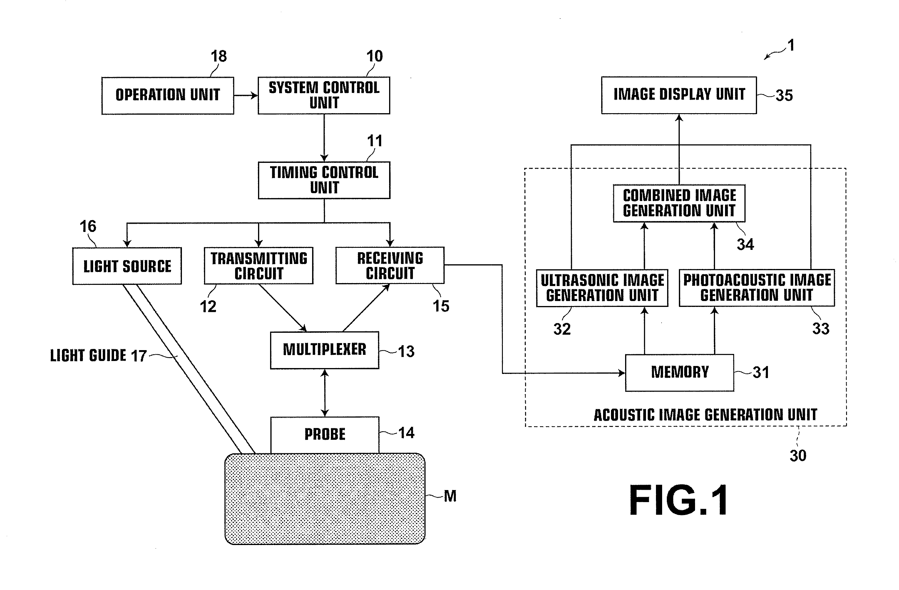
[0056]A first embodiment of the ultrasonic photoacoustic imaging apparatus and an operation method of the same will be described in detail. FIG. 1 is a block diagram of the ultrasonic photoacoustic imaging apparatus according to the first embodiment.

[0057]As illustrated in FIG. 1, ultrasonic photoacoustic imaging apparatus 1 of the present invention includes system control unit 10 for controlling the entire system, timing control unit 11 for controlling projection timings of an ultrasonic wave and light, as well as the timing of acoustic wave capturing period, transmitting circuit 12 for giving a predetermined delay time to a transmitting signal, multiplexer 13, and probe 14 which includes an array transducer having a plurality of transducers and is capable of projecting an ultrasonic wave into the inside of subject M and converting an acoustic wave propagating in the inside of subject M to an electrical s...

second embodiment

of Ultrasonic Photoacoustic Imaging Apparatus and Operation Method of the Same

[0089]A second embodiment of the ultrasonic photoacoustic imaging apparatus and operation method of the same will now be described in detail. FIG. 7 is a block diagram of the ultrasonic photoacoustic imaging apparatus according to the second embodiment. Second ultrasonic photoacoustic imaging apparatus 2 and operation method of the same are similar to those of the first embodiment. The second embodiment differs from the first embodiment in that operation unit 18 includes mode selection unit 19. Therefore, description will be made focusing on mode selection unit 19 and other components will not be elaborated upon further here unless otherwise specifically required.

[0090]Mode selection unit 19 allows selection between an ultrasonic mode in which only the ultrasonic image is generated and a photoacoustic mode in which only a photoacoustic image is generated. Further, mode selection unit 19 allows switching be...


PUM


Abstract

An ultrasonic photoacoustic imaging apparatus which includes a probe incorporating an array transducer having a plurality of transducers and an acoustic image generation unit that generates, based on a mixed signal obtained by converting an acoustic wave, in which an ultrasonic wave and a photoacoustic wave are mixed and making use of a difference between phase shift aspect of electrical signals of the ultrasonic waves from the same reflection source in the inside of the subject and phase shift aspect of electrical signals of the photoacoustic waves from the same generation source in the inside of the subject, an electrical signal reflecting the ultrasonic wave and an electrical signal reflecting the photoacoustic wave, and generates an ultrasonic image based on the electrical signal reflecting the ultrasonic wave and a photoacoustic image based on the electrical signal reflecting the photoacoustic wave.

Description

BACKGROUND OF THE INVENTION[0001]1. Field of the Invention[0002]The present invention relates to an ultrasonic photoacoustic imaging apparatus for generating an ultrasonic image by projecting an ultrasonic wave into an inside of a subject and detecting a ultrasonic wave reflected from the inside of the subject and generating a photoacoustic image by projecting light into the inside of a subject and detecting a photoacoustic wave generated in the inside of the subject. The invention also relates to an operation method of the same.[0003]2. Description of the Related Art[0004]As one of the methods of obtaining an internal tomographic image of a subject, an ultrasonic imaging is known in which an ultrasonic image is generated by projecting an ultrasonic wave into an inside of a subject and detecting an ultrasonic wave reflected from the inside of the subject, thereby obtaining a morphological internal tomographic image of the subject. In the mean time, development of devices for display...

Claims


Application Information

Patent Timeline
Patent Type & Authority Applications(United States)
IPC IPC(8): A61B6/00
CPCA61B8/4416A61B5/0095A61B5/0035
Inventor SATOH, YOSHIAKI
Owner FUJIFILM CORP
Why Eureka
Try Eureka