Medical apparatus and system

a medical device and system technology, applied in the field oftelemetry, can solve the problems of time-consuming and also unreliable methods, limited range of said removable antennas, and repeated tedious reception/transmission optimization, and achieve the effects of reliable radio communication, eliminating or eliminating or reducing the number o

Inactive Publication Date: 2009-05-21
ST JUDE MEDICAL
View PDF2 Cites 20 Cited by
  • Summary
  • Abstract
  • Description
  • Claims
  • Application Information

AI Technical Summary

Benefits of technology

[0009]An object of the present invention is to provide reliable radio communication within a telemetry system, the communication being easily and conveniently optimized, eliminating or at least reducing the risk of a communication failure between an implantable medical device and a monitoring device due to fading and / or a low signal strength.

Problems solved by technology

Therefore, should there arise a need to move a patient from one place to another, for example from an examination room to an X-ray examination room, the tedious reception / transmission optimization would have to be performed once more.
Thus, the apparatus described requires the physician operating it to perform a kind of an antenna reception optimization, which is a time-consuming and also unreliable method.
Further, the range of said removable antenna is limited, and dependent upon the length of a coiled cord by means of which the removable antenna is coupled to a transceiver within the programmer.
Furthermore, such a programmer is relatively expensive, and it would be desirable and convenient to be able to easily move the programmer, for example between different wards in a hospital, with retained communication quality, to thereby avoid having to buy several costly programmers.

Method used


Image

  • Medical apparatus and system
  • Medical apparatus and system
  • Medical apparatus and system

Examples


Embodiment Construction

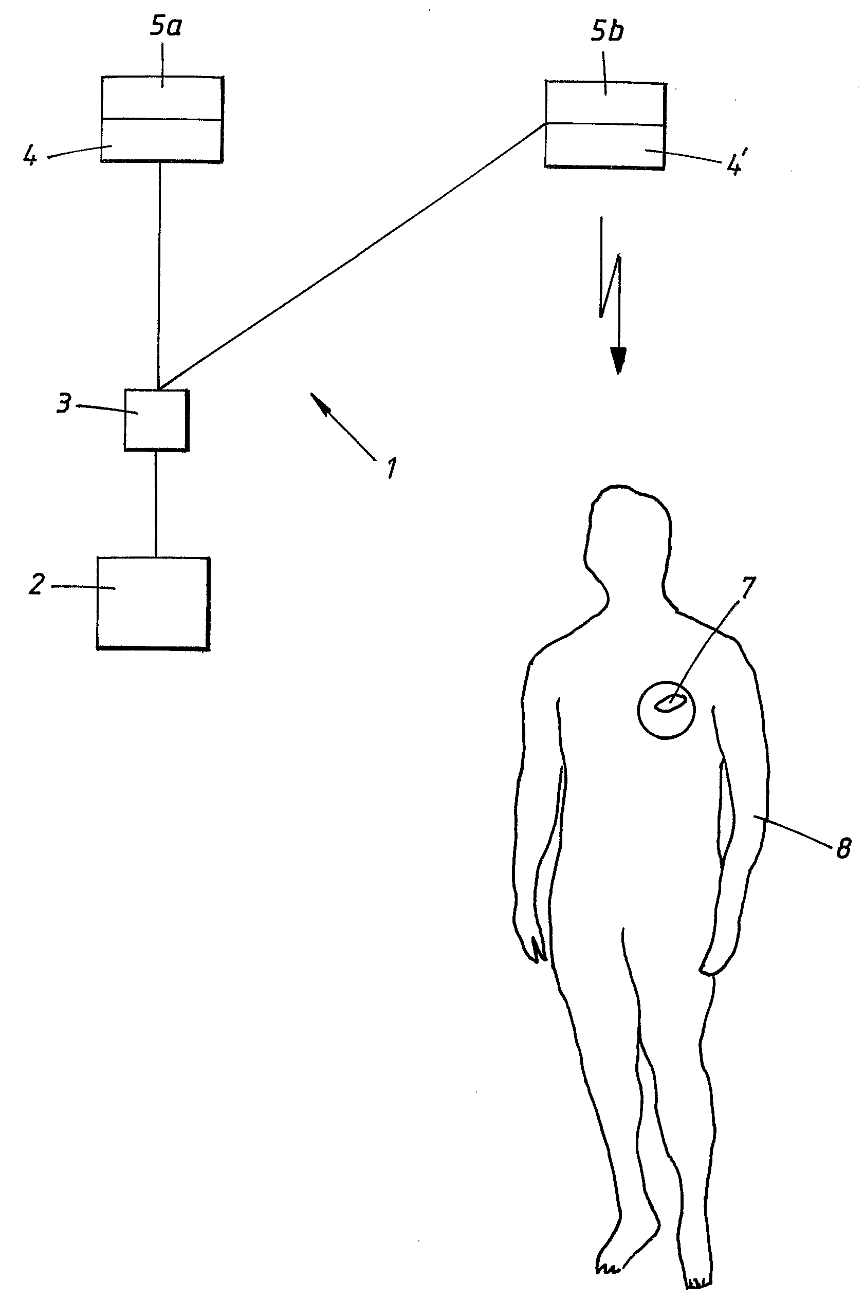
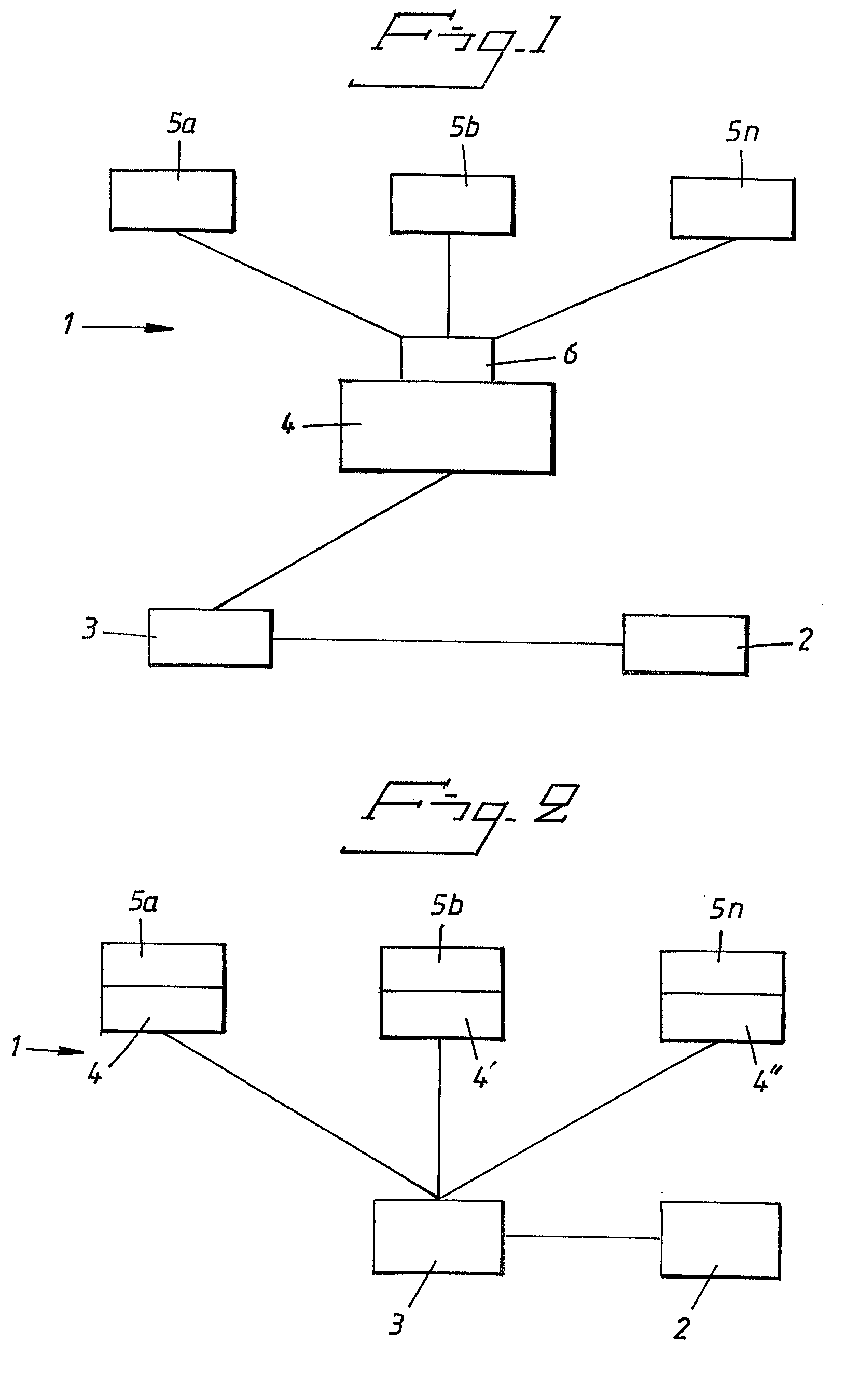
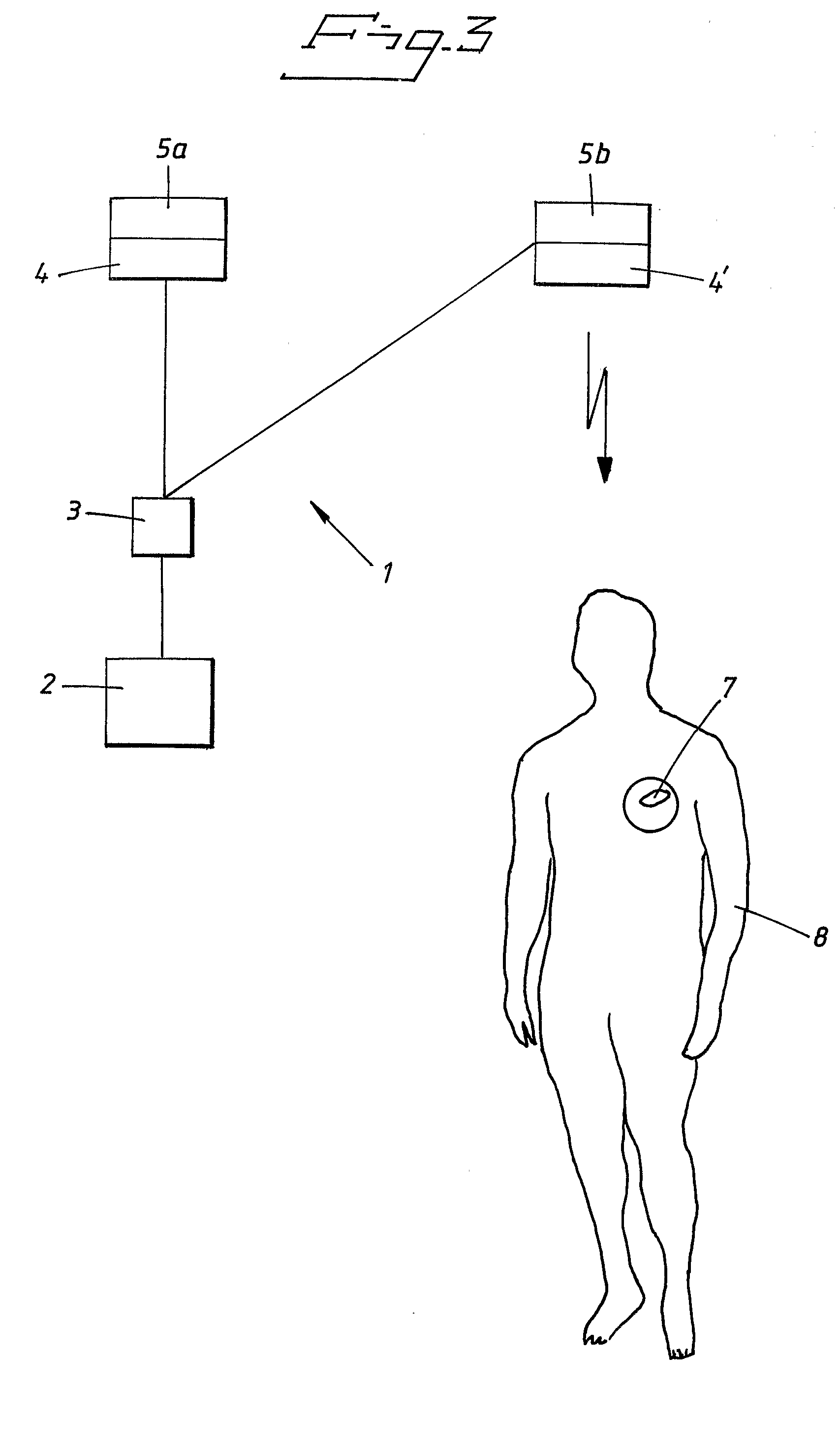
[0026]In the following description the same reference numerals will be used for equivalent or similar elements throughout the drawings. With reference first to FIG. 1, a schematic layout depicting an exemplary medical apparatus in accordance with the invention is shown. A medical apparatus 1 for programming and / or monitoring a patient related device 7 shown in FIG. 3, for example an implantable medical device, over a radio-based wireless network comprises a programmer or monitoring device 2, hereinafter referred to as a programmer 2. The programmer 2 is provided with input and / or output means for transmitting programming instructions to an implantable medical device, and / or for outputting monitoring information patient related data, for example for display on a screen, thereby enabling a physician to easily see such patient related data received from the implantable medical device.

[0027]A control unit 3, for example a microcontroller, is connected to the programmer 2, via wired stan...


PUM


Abstract

A medical system includes an implantable medical device configured for implantation in a living subject to interact with the subject, an extracorporeal device having a processor that processes information such as programming instructions for the implantable medical device or monitoring data received from the implantable medical device, and at least two antenna devices located at respectively different locations. The implantable medical device communicates with at least one of the two antenna devices, and the extracorporeal device also communicates with the at least two antenna devices to exchange the aforementioned information with the implantable medical device via at least one of the two antenna devices. The at least two antenna devices are physically separated from the extracorporeal device and the extracorporeal device communicates with each of the at least two antenna devices via a communication link that allows the extracorporeal device to be freely moved relative to the at least two antenna devices. The communication link can be a hard-wired communication link or a wireless communication link.

Description

BACKGROUND OF THE INVENTION[0001]1. Field of the Invention[0002]The present invention relates to the field of telemetry, and in particular to a medical apparatus for programming and / or monitoring an implantable medical device over a radio-based wireless network, and such a system.[0003]2. Description of the Prior Art[0004]Telemetry is a generic term for techniques for conveying measuring data from one point to another, usually by means of radio. In particular, within the medical field telemetry systems are generally used for enabling radio-frequency (RF) communication between an implantable medical device (IMD) such as a pacemaker, and an external monitoring device. The frequency spectrum used for wireless communications between implanted medical devices and external equipment is about 400 MHz, but for wireless medical telemetry services in general several frequency bands may be used. Within a medical telemetry system crucial physiologic data is transmitted, and it is critical to en...

Claims


Application Information

Patent Timeline
Patent Type & Authority Applications(United States)
IPC IPC(8): A61N1/08
CPCA61B5/0031A61N1/37229A61N1/08
Inventor SNITTING, TOMASSKOOG, VIKTORABRAHAMSON, HANS
Owner ST JUDE MEDICAL
Why Eureka
Try Eureka