
Current-Fed Push-Pull Converter with Passive Voltage Clamp

a current-fed push-pull converter and voltage clamp technology, applied in the field of electrosurgical systems, can solve the problems of tissue destruction, prolonging healing, and affecting the effect of tissue impedance change,

Active Publication Date: 2011-12-29
TYCO HEALTHCARE GRP LP
View PDF4 Cites 30 Cited by
  • Summary
  • Abstract
  • Description
  • Claims
  • Application Information

AI Technical Summary

Benefits of technology

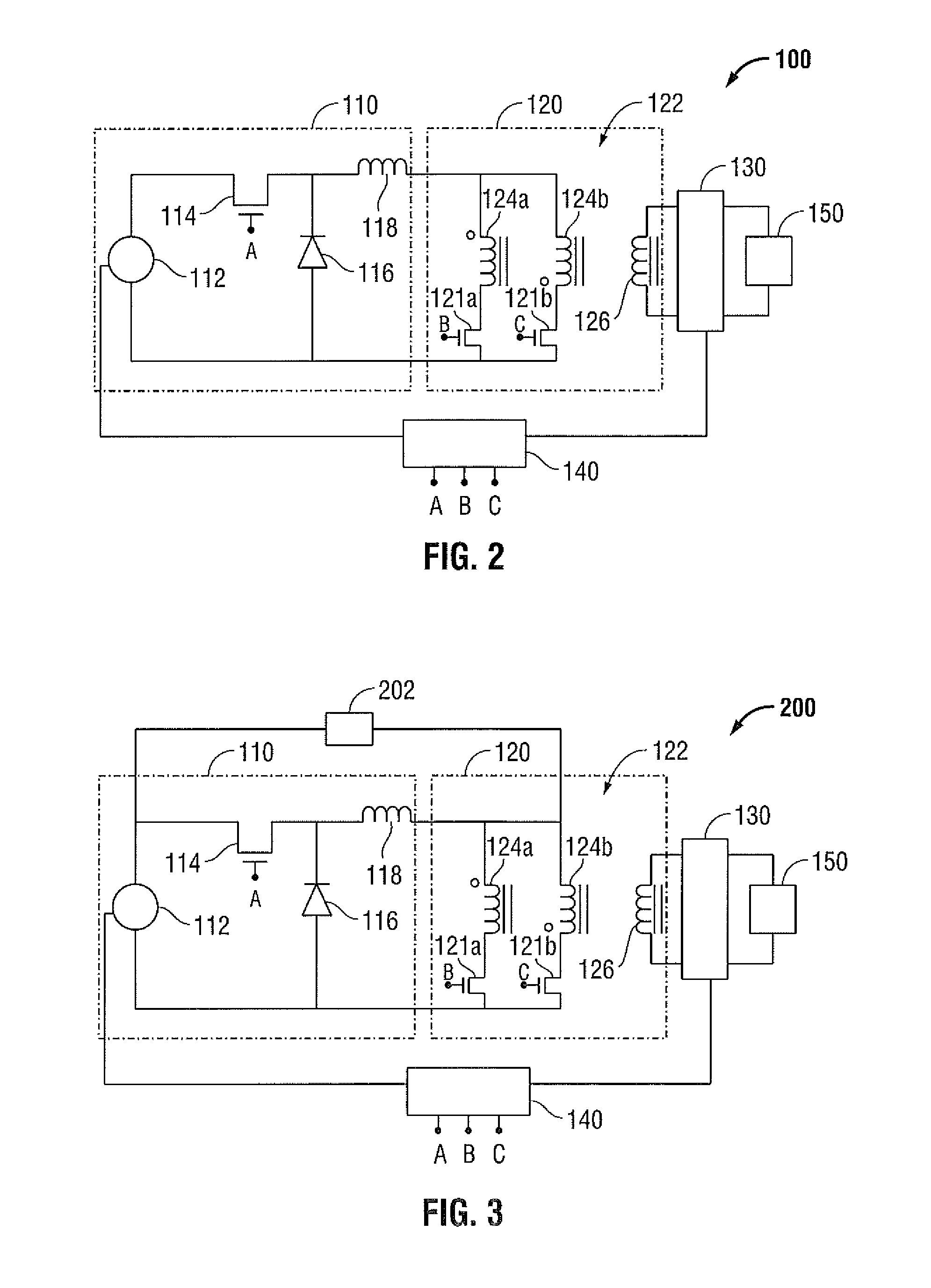
The present disclosure provides an electrosurgical generator that produces RF energy with a current-source type behavior. The generator includes a buck converter, an RF stage, and an active element. The RF stage includes a transformer with primary and secondary windings. The generator also has a sensor circuit to measure various parameters of the RF energy, and a controller to control the output of the generator based on the measured parameters. The technical effects of this invention include improved control over the output of RF energy and better accuracy in measuring various parameters.

Problems solved by technology

Applying more electrosurgical power than necessary results in tissue destruction and prolongs healing.
Moreover, the same tissue type can be desiccated during electrosurgical treatment and thus the tissue impedance will change dramatically in the space of a very brief time.
A current-source type generator has a disadvantage in that, as the impedance of the tissue increases, the open-circuit voltage may reach unacceptably high levels.

Method used


Image

  • Current-Fed Push-Pull Converter with Passive Voltage Clamp
  • Current-Fed Push-Pull Converter with Passive Voltage Clamp
  • Current-Fed Push-Pull Converter with Passive Voltage Clamp

Examples


Embodiment Construction

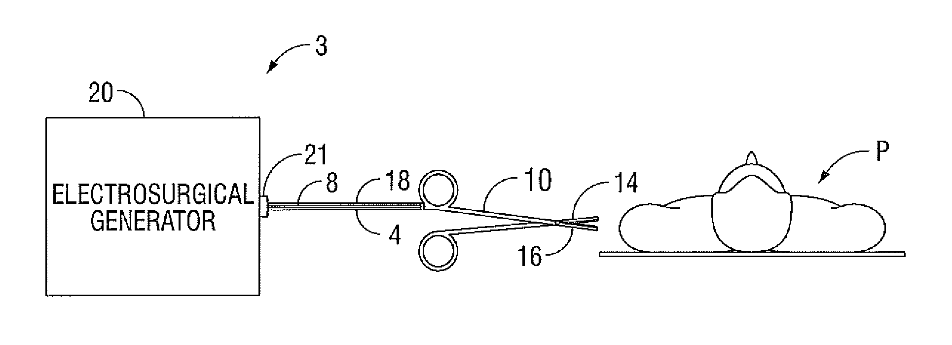
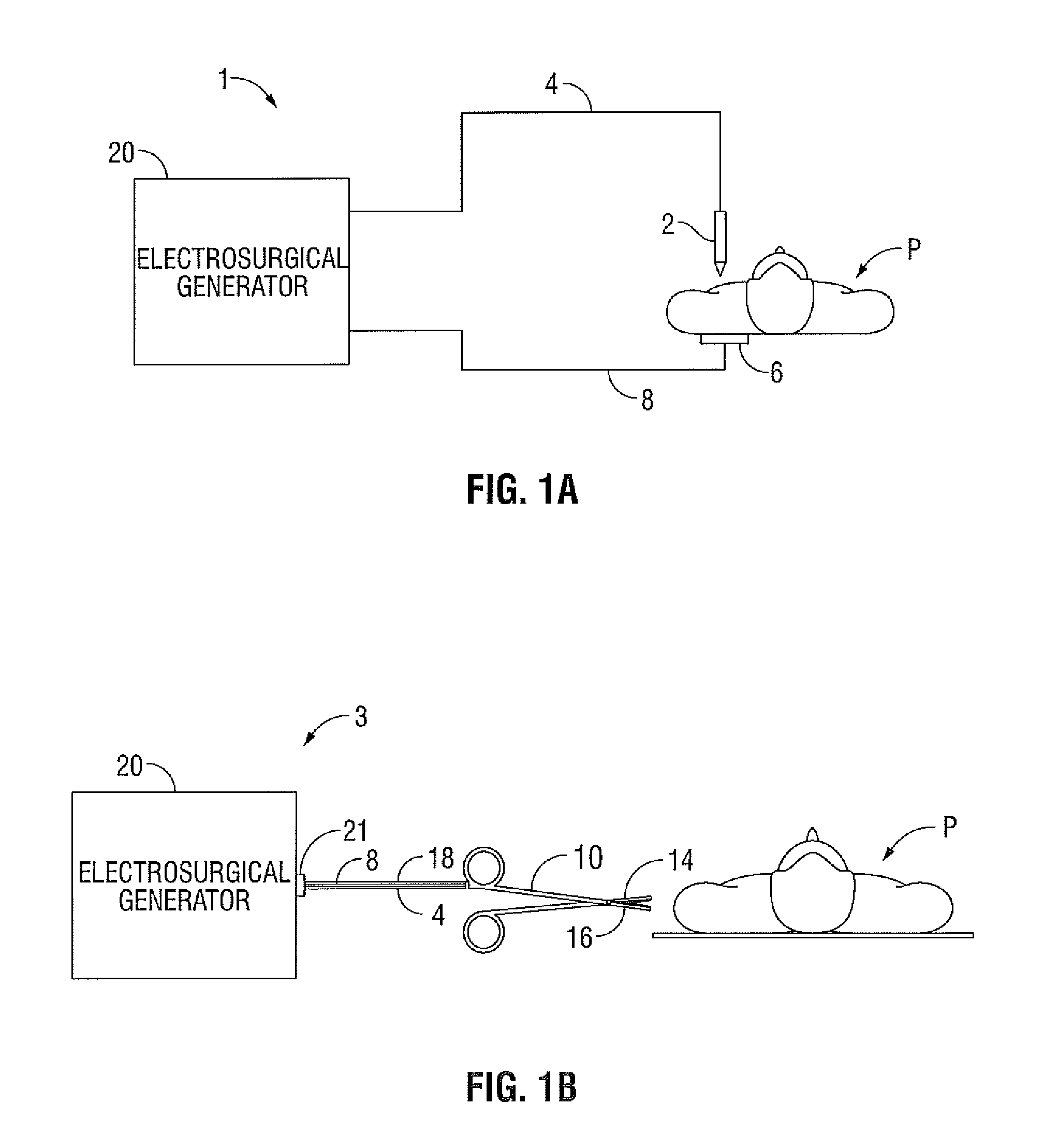
[0020]Particular embodiments of the present disclosure are described hereinbelow with reference to the accompanying drawings; however, it is to be understood that the disclosed embodiments are merely exemplary of the disclosure, which may be embodied in various forms. Well-known functions or constructions are not described in detail to avoid obscuring the present disclosure in unnecessary detail. Therefore, specific structural and functional details disclosed herein are not to be interpreted as limiting, but merely as a basis for the claims and as a representative basis for teaching one skilled in the art to variously employ the present disclosure in virtually any appropriately detailed structure. Like reference numerals may refer to similar or identical elements throughout the description of the figures.

[0021]The generator according to the present disclosure can perform ablation, monopolar and bipolar electrosurgical procedures, including vessel sealing procedures. The generator ma...


PUM


Abstract

An electrosurgical generator configured to output radio frequency (RF) energy having a current-source type behavior is provided. The generator has a buck converter having a voltage source, at least one switch and an inductor. The generator also has an RF stage configured to output the RF energy. A sensor circuit configured to measure at least one parameter of the RF energy and a controller configured to receive the measured parameter from the sensor circuit and control the output of the electrosurgical generator based on the measured parameter may also be provided in the electrosurgical generator.

Description

BACKGROUND[0001]1. Technical Field[0002]The present disclosure is directed to electrosurgical systems, and, in particular, to an electrosurgical system having a radio frequency (RF) output with a current-source type behavior.[0003]2. Description of the Related Art[0004]An electrosurgical generator is used in surgical procedures to deliver electrical energy to the tissue of a patient. When an electrode is connected to the generator, the electrode can be used for cutting, coagulating or sealing the tissue of a patient with high frequency electrical energy. During normal operation, alternating electrical current from the generator flows between an active electrode and a return electrode by passing through the tissue and bodily fluids of a patient.[0005]The electrical energy usually has a waveform shaped to enhance its ability to cut, coagulate or seal tissue. Different waveforms correspond to different modes of operation of the generator, and each mode gives the surgeon various operati...

Claims


Application Information

Patent Timeline
Patent Type & Authority Applications(United States)
IPC IPC(8): A61B18/18
CPCA61B18/1206A61B18/18A61B18/1442A61B18/16A61B2018/00345A61B2018/00404A61B2018/00577A61B2018/00619A61B2018/00642A61B2018/0066A61B2018/00702A61B2018/00779A61B2018/00827A61B2018/00875A61B2018/00892A61B2018/00958A61B18/1233
Inventor JOHNSTON, MARK A.
Owner TYCO HEALTHCARE GRP LP
Learn More