Electronic device and method for controlling unmanned aerial vehicle using the same

a technology of electronic devices and unmanned aerial vehicles, applied in the field of electric devices and methods for controlling unmanned aerial vehicles (uavs) using the same, can solve problems such as inefficiency in controlling the uav

Active Publication Date: 2011-12-29
BEIJING JINGDONG CENTURY TRADING CO LTD
View PDF7 Cites 89 Cited by
  • Summary
  • Abstract
  • Description
  • Claims
  • Application Information

AI Technical Summary

Problems solved by technology

Accordingly, it is inefficient to control the UAV.

Method used


Image

  • Electronic device and method for controlling unmanned aerial vehicle using the same
  • Electronic device and method for controlling unmanned aerial vehicle using the same
  • Electronic device and method for controlling unmanned aerial vehicle using the same

Examples


first embodiment

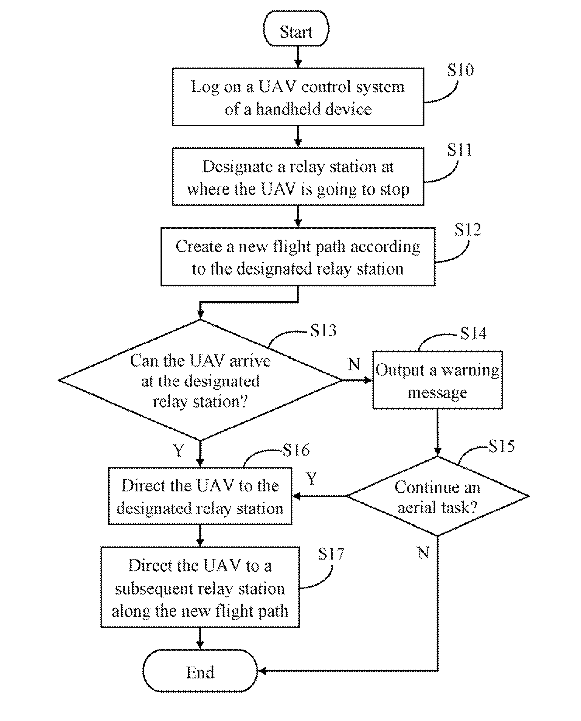
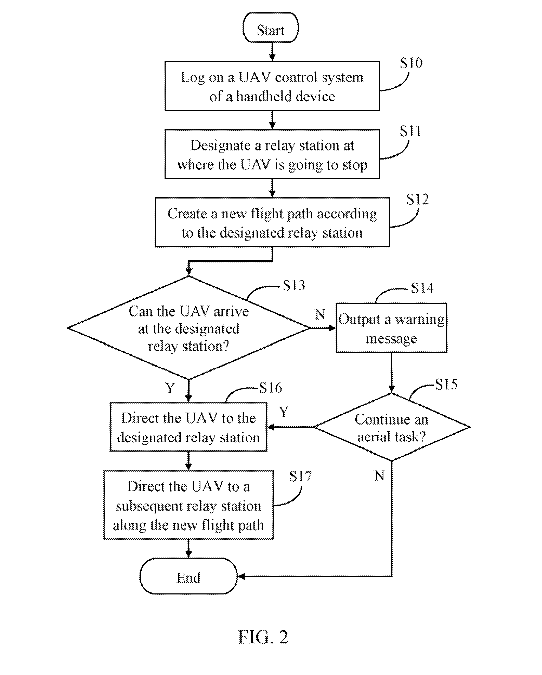
[0017]FIG. 2 is a flowchart of a method for controlling an unmanned aerial vehicle using the electronic device 2. The method in FIG. 2 may be performed by the electronic device (e.g. a mobile phone) having a touch-sensitive display with a graphical user interface (GUI), at least one processor, a storage device and one or more modules, programs or sets of instructions stored in the storage device for performing the method in FIG. 2. In one embodiment, the electronic device provides a number of functions, including wireless communication, for example. Depending on the embodiment, additional blocks may be added, others removed, and the ordering of the blocks may be changed.

[0018]In block S10, a user logs on the UAV control system 20 of the electronic device 2 (as shown in FIG. 4). In one embodiment, two function buttons are presented on the display screen 22 of the electronic device 2. As shown in FIG. 5, a first function button to designate a relay station and a second function button...

second embodiment

[0028]FIG. 3 is a flowchart of a method for controlling an unmanned aerial vehicle using the electronic device 2. The method in FIG. 3 may be performed by an electronic device (e.g. a mobile phone) having a touch-sensitive display with a graphical user interface (GUI), at least one processor, a storage device and one or more modules, programs or sets of instructions stored in the storage device for performing the method in FIG. 3. In one embodiment, the electronic device provides a number of functions, including wireless communication, for example. Depending on the embodiment, additional blocks may be added, others removed, and the ordering of the blocks may be changed.

[0029]In block S20, a user logs on the UAV control system 20 of the electronic device (as shown FIG. 4) 2. As shown in FIG. 10, in the second embodiment of the method for controlling the UAV, the user selects the second button of “draw a flight section.” In one embodiment, the flight section is a sub-part of a flight ...


PUM


Abstract

A method for controlling an unmanned aerial vehicle (UAV) using an electronic device determines a designated relay station of the UAV using the electronic device, and creates a new flight path for the UAV according to the designated relay station. The method further directs the UAV to fly to the designated relay station upon the condition that the UAV can arrive at the designated relay station, and directs the UAV to fly to a subsequent relay station along the new flight path upon the condition that the UAV has not arrived at an endpoint of the new flight path.

Description

BACKGROUND[0001]1. Technical Field[0002]Embodiments of the present disclosure relate to helicopter control technology, and particularly to an electronic device and method for controlling an unmanned aerial vehicle (UAV) using the electronic device.[0003]2. Description of Related Art[0004]UAVs have been used to perform security surveillance by capturing images of a number of monitored scenes, and sending the captured images to a monitoring computer.[0005]However, a flight path of the UAV needs to be changed using a special control software installed in the monitoring computer. That is to say, if an administrator wants to change the flight path of the UAV, the administrator has to go back to the monitoring computer. Accordingly, it is inefficient to control the UAV. Therefore, an efficient method for controlling the flight status of the UAV is desired.BRIEF DESCRIPTION OF THE DRAWINGS[0006]FIG. 1 is a block diagram of one embodiment of an electronic device.[0007]FIG. 2 is a flowchart ...

Claims


Application Information

Patent Timeline
Patent Type & Authority Applications(United States)
IPC IPC(8): G05D1/00
CPCG05D1/0016G05D1/0011
Inventor LEE, HOU-HSIENLEE, CHANG-JUNGLO, CHIH-PING
Owner BEIJING JINGDONG CENTURY TRADING CO LTD
Why Eureka
Try Eureka