
Grinder

a grinder and grinding wheel technology, applied in the field of grinders, can solve the problems of long service life and fail-safe operation, and achieve the effects of convenient grinding and smooth operation, good grinding effect, and good transport

Inactive Publication Date: 2012-01-05
SEVERIN ELEKTROGERATE
View PDF10 Cites 10 Cited by
  • Summary
  • Abstract
  • Description
  • Claims
  • Application Information

AI Technical Summary

Benefits of technology

[0008]Another object is the provision of such an improved grinder that overcomes the above-given disadvantages, in particular wherein the bending loads on the grinding disks are avoided to the largest possible extent and a consistent grinding degree of the ground material is achieved.
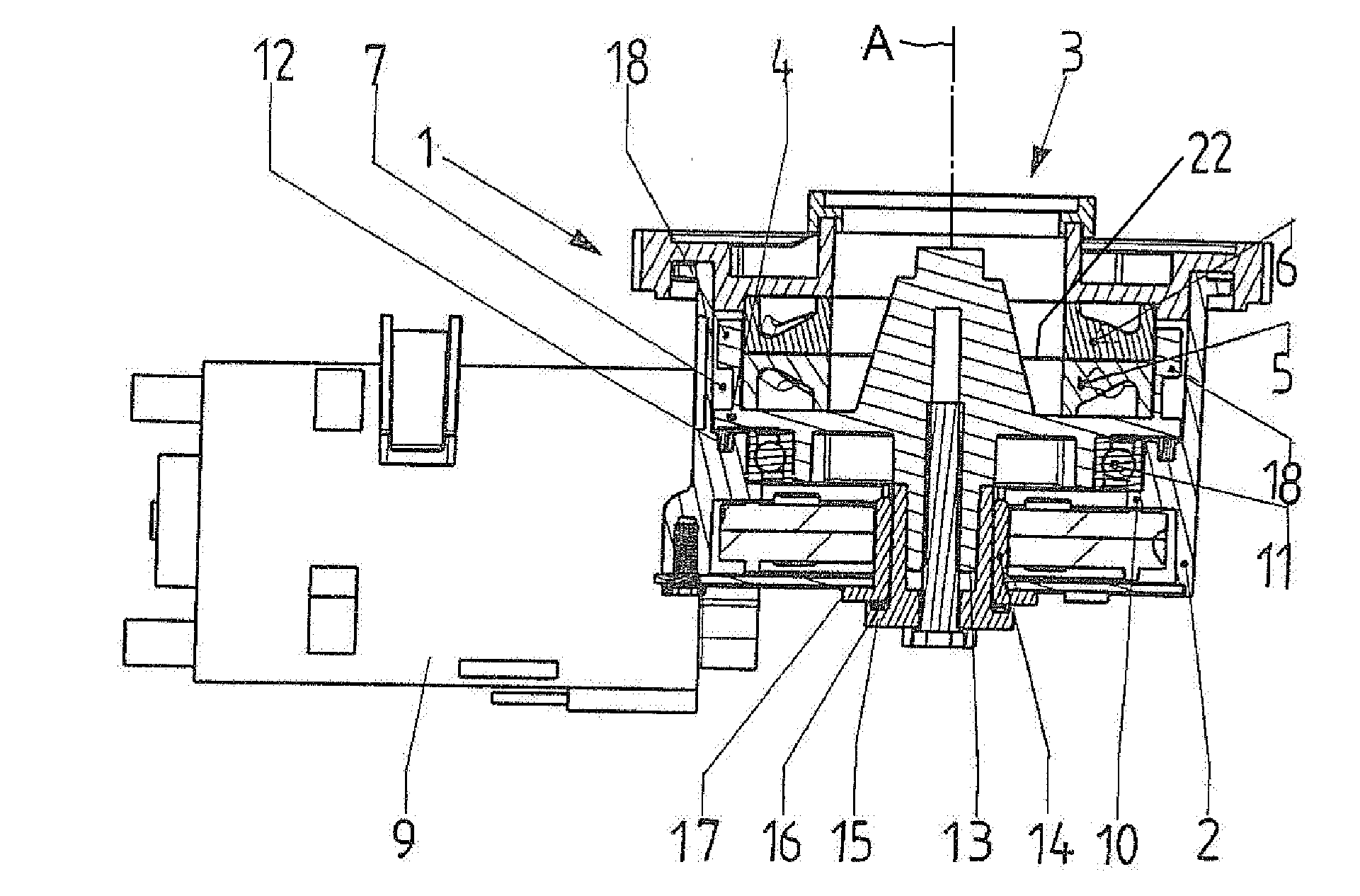
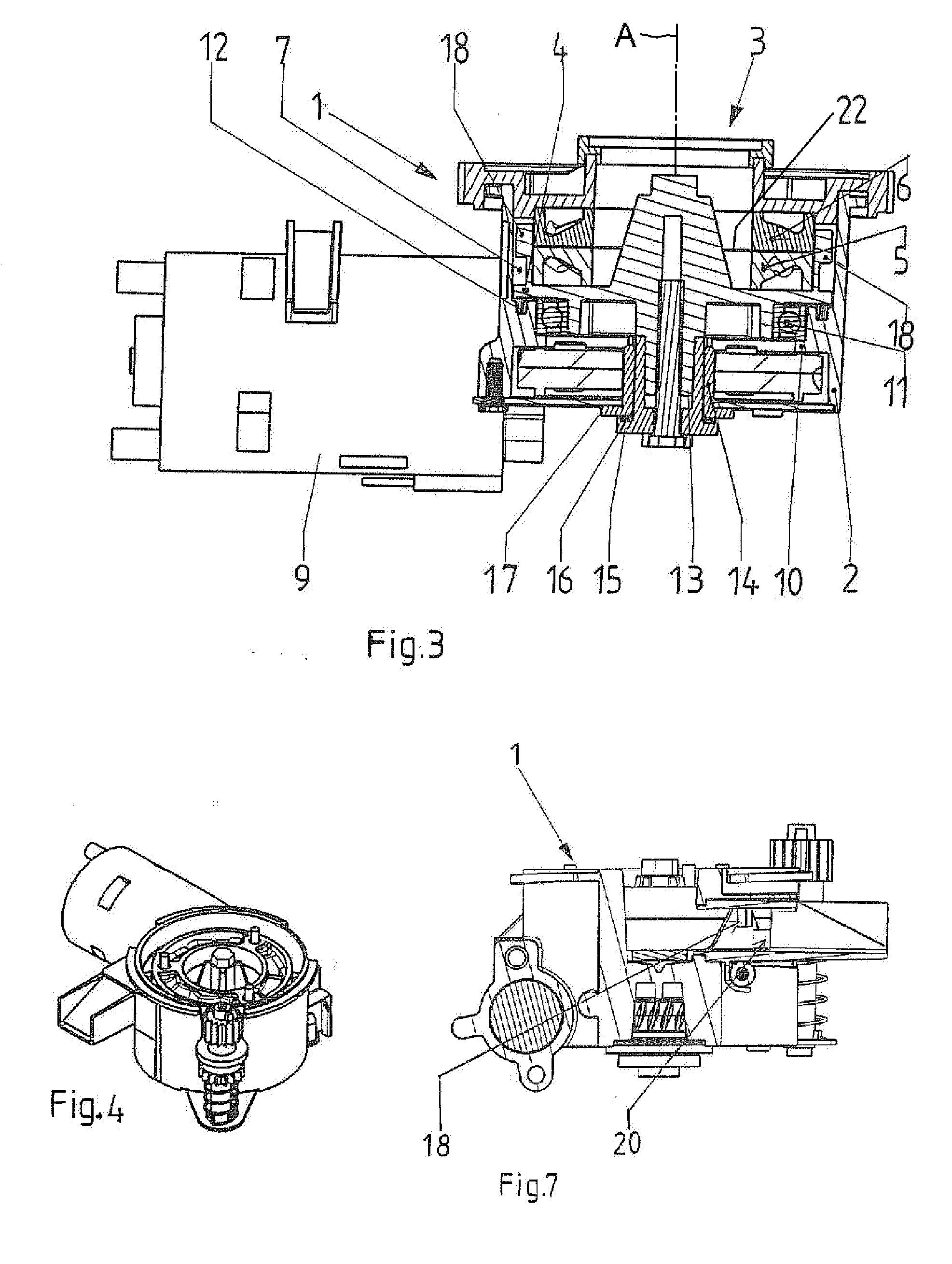
[0011]Due to the fact that the angular-contact bearings are directly below the annular grinding disks, and not centered but relatively far in the radial direction toward the outside, during operation of the grinder, the grinding disks are directly supported by the bearing so that an excellent mounting is achieved by means of which size fluctuations of the grinding gap between the disks are prevented. As a result, more uniform grind is achieved during grinding. Moreover, this configuration ensures that bending loads on the support and the grinding disks are avoided, resulting in a longer service life and fail-safe operation. Also, these measures allow the grinder, while achieving a better grinding degree consistency, to be made smaller, lighter and / or from better materials.
[0013]To prevent that grinds from getting into the region of the bearing arrangement the housing is formed with an annular groove holding a sealing ring, preferably a felt ring, adjacent a lower face of the support and radially outward of the angular-contact bearing. This felt seal ring protects the bearing from ground particles.
[0014]To ensure good smoothness of operation of the grinder and to guarantee exact guidance of the support the support engages with a shaft projection through the bottom of the housing. This the shaft projection is mounted in a bearing sleeve fixed to the housing and, with interposition of a slide bearing, e.g. a spring ring, is axially supported with a collar on a collar of the bearing sleeve. This facilitates the smooth operation of the grinder.
[0015]For complete transport of the ground material, pusher elements engage with the gap and are fixed to the support or integrally formed with it. Rotation of the support makes the elements move the ground material in the chamber to an output opening of the housing. For transporting the ground material, a deflector is provided on the support to divert the ground material orbiting in the chamber to the output. This ensures that the chamber can be of small axial and radial dimensions with good transport of the ground material and a complete evacuation of the ground material. This deflector nose is preferably provided on the housing directly downstream of the output port, relative to the rotation direction of the support.
[0016]As a result, the ground material transported by the pushers is conveyed with high reliability to the output because the nose or deflector diverts the ground material carried along by the pushers to the output, thus into the output tube. Thus improved transport is achieved so that fresh ground material is delivered at any time and no blockages, overheating or overgrinding due to ground material remaining in the gap result.

Problems solved by technology

Moreover, this configuration ensures that bending loads on the support and the grinding disks are avoided, resulting in a longer service life and fail-safe operation.

Method used


Image

  • Grinder
  • Grinder
  • Grinder

Examples


Embodiment Construction

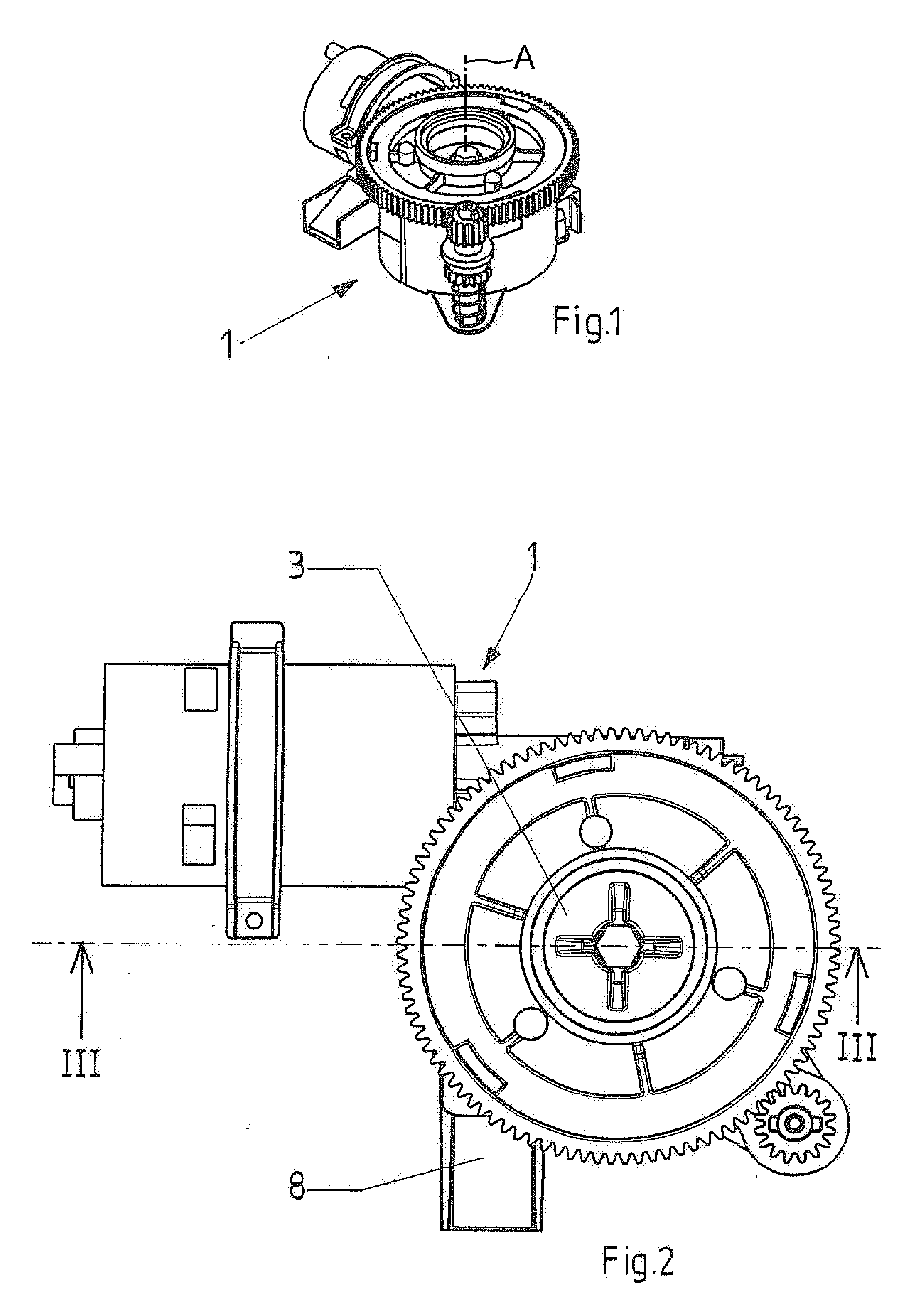
[0025]A grinder 1 for material such as coffee beans has a housing 2 that in use has an upwardly open fill or input opening 3 for material to be ground. A one-piece support 4 is rotatable in the housing 2 about a vertical axis A and carries an annular grinding disk or ring 5 that is centered on the axis A and that has unillustrated upwardly directed small teeth. Above the lower grinding disk 5 fixed on the support 4, an upper annular grinding disk or ring 6 having unillustrated downwardly projecting small teeth is fixed on the housing 2 so that it cannot rotate or move axially. The two grinding disks 5 and 6 define a small grinding gap 22 that is radially inwardly and radially outwardly open and that lies in a plane perpendicular to the axis A.

[0026]The material to be ground thus is deflected into the radial inner periphery of the annular grinding gap 22 by a frustoconical upper part of the support 4, is comminuted between the disks 5 and 6, and the resultant particles are ejected ra...


PUM


Abstract

A grinder has a hollow housing, a support rotatable in the housing about an upright axis, a lower annular grinding disk fixed atop and rotatable with the support, and an upper grinding disk nonrotatably fixed in the housing above the lower disk and forming therewith a radially extending annular grinding gap. The disks form with the housing an annular outlet chamber into which the gap opens radially outwardly. The housing forms an upwardly open intake into which the gap opens radially inward. An electrical drive is connected to the support for rotating the support and lower disk in the housing so that material charged into the intake is ground in the gap and expelled as particles into the output chamber. An angular-contact bearing is braced axially and radially between the support and the housing below the disks.

Description

FIELD OF THE INVENTION[0001]The present invention relates to a grinder. More particularly this invention concerns a coffee grinder.BACKGROUND OF THE INVENTION[0002]A standard grinder, in particular for coffee beans, has a housing, a support rotatably mounted in the housing about an axis and on which a lower annular grinding disk is fixed, an upper annular grinding disk that is nonrotatably fixed in the housing, an upper housing opening for input of material to be ground, a radially or tangentially outwardly open output opening formed on the housing for ground material, and an electric drive for rotating the support.[0003]Such grinders are known from the prior art. These grinders work with two annular grinding disks or rings. One of the grinding disks is stationary and the other grinding disk rotates and is coupled through the support to the electric drive. The material to be ground is loaded centrally and axially from above via an opening into the housing. A cone on the support prot...

Claims


Application Information

Patent Timeline
IPC IPC(8): A47J42/12
CPCA47J42/16
Inventor KROESEN, KLAUSBEULE, SEBASTIAN
Owner SEVERIN ELEKTROGERATE
Learn More