Lighting Control System

a control system and control technology, applied in the direction of process and machine control, data switching networks, instruments, etc., can solve the problems of difficult cost effective control of such a visible light communication network, data cannot be communicated through walls between various rooms in a building, etc., and achieve the effect of no additional cos

Inactive Publication Date: 2012-01-05
LUTRON TECH CO LLC
View PDF6 Cites 111 Cited by
  • Summary
  • Abstract
  • Description
  • Claims
  • Application Information

AI Technical Summary

Benefits of technology

[0020]Using visible light to communicate between lamps and other devices in a lighting system has many advantages over wired, wireless, and powerline communication networks such as those previously described. No dedicated wires are needed, which is important especially for installation in existing buildings. The visible light spectrum is unregulated globally and does not suffer from the congestion and interference common in RF wireless communication. Electrical noise on the powerline, from appliances turning on and off for instance, does n

Problems solved by technology

A limitation of such a visible light communication protocol is that data cannot be communicated through walls between various rooms in a building.
A

Method used


Image

  • Lighting Control System
  • Lighting Control System
  • Lighting Control System

Examples


Embodiment Construction

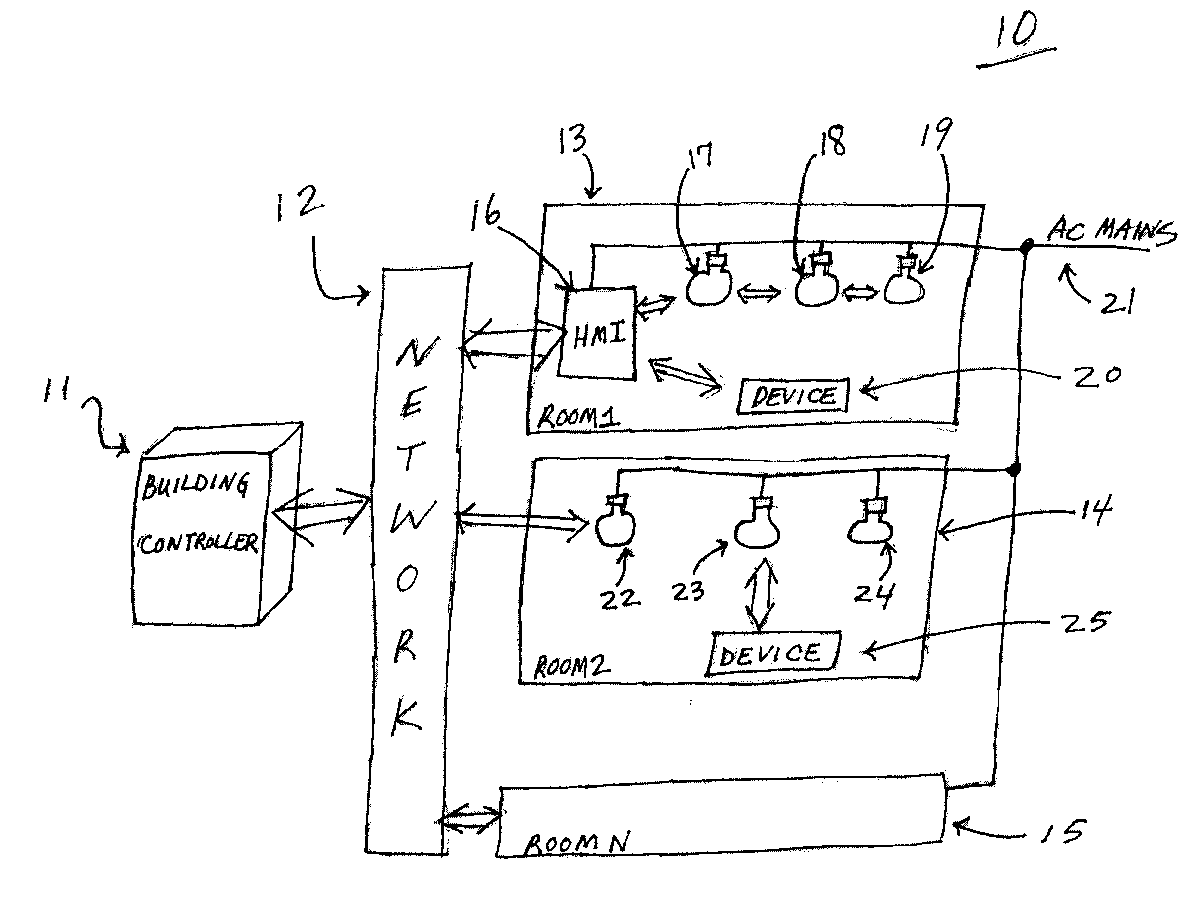
[0039]Turning now to the drawings, FIG. 1 is one example of a building lighting system 10 that comprises building controller 11 and network 12 that connects room113, room214, and roomN 15 to building controller 11. The designation room1 through roomN represent any number of rooms in a building or even multiple buildings to one of more central controllers represented by building controller 11. Within any particular room, represented by room113 for instance, lamps 17, 18, and 19 communicate with each other and HMI 16 through modulated visible light shown in bi-directional arrows. In this example room113, HMI 16 additionally interfaces between network 12, lamps 17, 18, and 19, and wireless communication device 20. Wireless communication device 20 may or may not be part of building lighting system 10, but if included, can be any type of mobile device including but not limited to mobile phones, smart phones, personal digital assistants (PDA), and mobile computers such as netbooks, notebo...


PUM


Abstract

Intelligent illumination device are disclosed that use components in an LED light to perform one or more of a wide variety of desirable lighting functions for very low cost. The LEDs that produce light can be periodically turned off momentarily, for example, for a duration that the human eye cannot perceive, in order for the light to receive commands optically. The optically transmitted commands can be sent to the light, for example, using a remove control device. The illumination device can use the LEDs that are currently off to receive the data and then configure the light accordingly, or to measure light. Such light can be ambient light for a photosensor function, or light from other LEDs in the illumination device to adjust the color mix.

Description

PRIORITY CLAIM[0001]The present application is a continuation-in part of U.S. patent application Ser. No. 12 / 924,628 filed Sep. 30, 2010 which claims priority to the following: (1) U.S. Provisional Patent Application No. 61 / 277,871 filed Sep. 30, 2009; (2) U.S. Provisional Patent Application No. 61 / 281,046 filed Nov. 12, 2009; (3) U.S. Provisional Patent Application No. 61 / 336,242 filed Jan. 19, 2010; (4) U.S. Provisional Patent Application No. 61 / 339,273 filed Mar. 2, 2010; which is further a continuation-in-part of U.S. patent application Ser. Nos. 12 / 806,114; 12 / 806,117; 12 / 806,121; 12 / 806,118; 12 / 806,126; 12 / 806,113, all filed Aug. 5, 2010, all of which claim priority to: (1) U.S. Provisional Patent Application No. 61 / 273,518 filed Aug. 5, 2009; (2) U.S. Provisional Patent Application No. 61 / 273,536 filed Aug. 5, 2009; (3) U.S. Provisional Patent Application No. 61 / 277,871 filed Sep. 30, 2009; (4) U.S. Provisional Patent Application No. 61 / 281,046 filed Nov. 12, 2009; (5) U.S. P...

Claims


Application Information

Patent Timeline
IPC IPC(8): H05B37/02
CPCH04L12/282H04L12/40013H04L12/413H04L12/43H04L12/437Y02B20/48H04L12/66H05B37/0245H04L2012/285H04B10/116H04L12/6418H05B47/175H05B47/19Y02B20/40H05B47/195
Inventor KNAPP, DAVID J.HO, HORACE C.LEWIS, JASON
Owner LUTRON TECH CO LLC
Why Eureka
Try Eureka