Coordinate input apparatus, light receiving apparatus of the coordinate input apparatus, and manufacturing method of the same

a technology of coordinate input and light receiving apparatus, which is applied in the direction of metal working apparatus, manufacturing tools, instruments, etc., can solve the problems of deteriorating operability, difficult to determine, and no normal operation may be performed any longer, and achieves high-reliability coordinate input apparatuses, high-quality manufacturing methods, and increased accuracy of position detection and touch determination.

Inactive Publication Date: 2012-01-05
CANON KK
View PDF17 Cites 21 Cited by
  • Summary
  • Abstract
  • Description
  • Claims
  • Application Information

AI Technical Summary

Benefits of technology

[0018]The present invention provides a coordinate input apparatus capable of inexpensively increasing the accuracy of position detection and the accuracy of touch determination, a light receiving apparatus for use in the coordinate input apparatus, and a manufacturing method of manufacturing a highly reliable coordinate input apparatus.
[0022]The present invention can provide a coordinate input apparatus capable of inexpensively increasing the accuracy of position detection and the accuracy of touch determination, a light receiving apparatus for use in the coordinate input apparatus, and a manufacturing method of manufacturing a highly reliable coordinate input apparatus.

Problems solved by technology

If this range is exceeded, no normal operation may be performed any longer because, for example, electric charge overflows.
However, it is very difficult to determine, from an out-of-focus image sensing signal, whether the pointing tool has actually touched the coordinate input surface, and only rough determination is possible.
This touch determination error causes an operation not intended by the operator, and hence significantly deteriorates the operability.
Unfortunately, this optical system includes lenses and optical elements having complicated shapes, or additionally includes an auto-focusing mechanism, and is difficult to inexpensively manufacture.
In other words, a distance range to be detected changes in accordance with the specifications of each product, and this makes it difficult to use common parts in light receiving optical systems, and makes inexpensive manufacture impossible.
Moreover, the settings of jigs and tools for adjusting the optical axis and focus point of an optical system must be changed in accordance with the size of a coordinate input apparatus, and this unavoidably increases the number of assembly steps.
Also, when the size of the coordinate input apparatus increases, the sizes of the jigs and tools increase accordingly, and this poses the problem of an installation space.
In addition, the adjustment of the jigs and tools requires a considerable precision, and as a consequence the productivity decreases.

Method used


Image

  • Coordinate input apparatus, light receiving apparatus of the coordinate input apparatus, and manufacturing method of the same
  • Coordinate input apparatus, light receiving apparatus of the coordinate input apparatus, and manufacturing method of the same
  • Coordinate input apparatus, light receiving apparatus of the coordinate input apparatus, and manufacturing method of the same

Examples


first embodiment

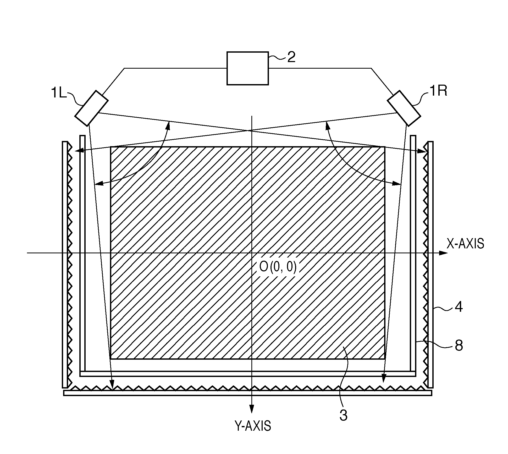
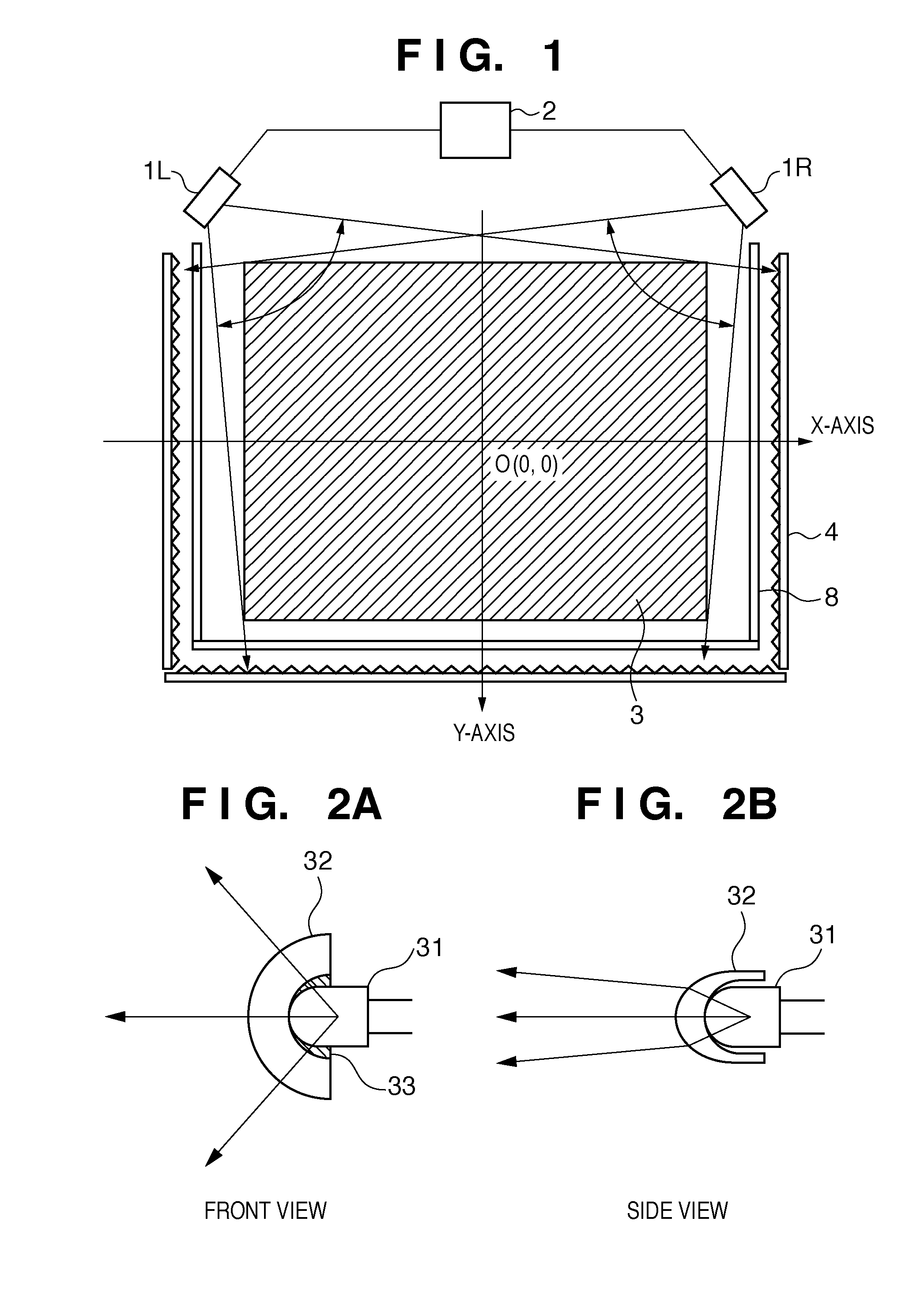
[0057]First, an outline of the arrangement of a coordinate input apparatus according to the present invention will be explained below with reference to FIG. 1.

[0058]FIG. 1 is a view showing an outline of the arrangement of an optical coordinate input apparatus of the first embodiment.

[0059]In FIG. 1, reference numerals 1L and 1R denote sensor units each including a light projecting unit and light receiving unit (light receiving apparatus). In the first embodiment as shown in FIG. 1, the sensor units 1L and 1R are arranged at a predetermined distance at positions (corners) parallel to the X-axis of a coordinate input effective region 3 as a coordinate input surface and symmetrical with respect to the Y-axis. The sensor units 1L and 1R are connected to a control / arithmetic unit 2, receive control signals from the control / arithmetic unit 2, and transmit detected signals to the control / arithmetic unit 2.

[0060]Reference numeral 4 denotes a retroreflecting member having a retroreflecting ...

second embodiment

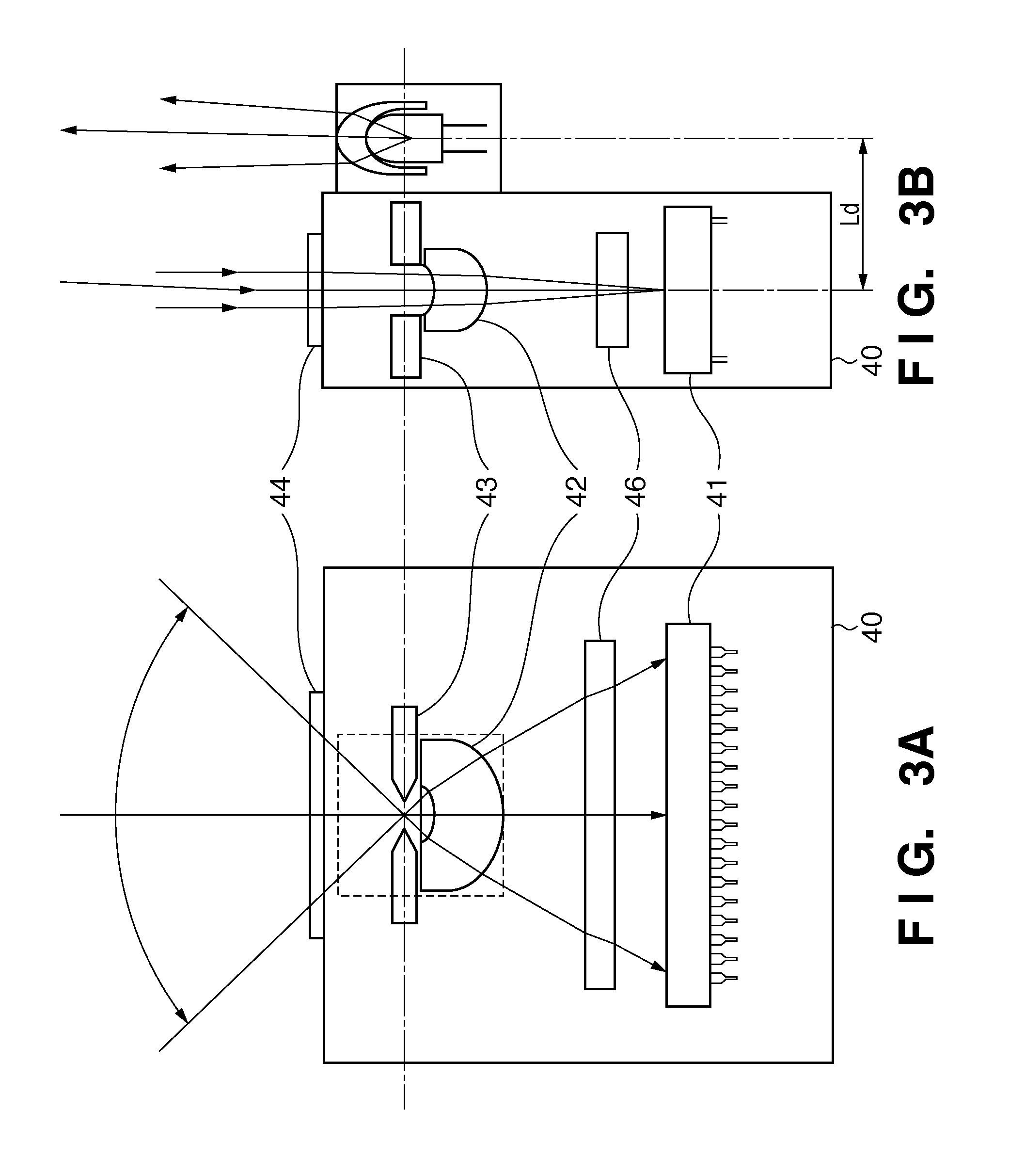
[0186]In the first embodiment, after the focus is adjusted to the predetermined distance LmaxBase from the sensor unit 1L (1R), the light transmissive plate 46 having the thickness d is attached in accordance with the size of the coordinate input effective region of the coordinate input apparatus, that is, the farthest point distance Lmax from the sensor unit. The performance and quality of coordinate input apparatuses having various sizes can be stabilized by selecting the thickness d of the light transmissive plate 46 to be attached.

[0187]As the second embodiment, an arrangement that improves the reliability of touch determination by optimizing the focusing state at the farthest point distance Lmax will be explained below.

[0188]As shown in FIGS. 3A and 3B, a light receiving optical system of a sensor unit 1L (1R) is a single-lens condenser optical system using a light receiving lens 42. To correct an optical error such as the aberration of a lens, it is generally necessary to form...

third embodiment

[0195]The first and second embodiments have been explained from the viewpoint of common parts and common optical adjustment by noting focusing and touch determination without depending on the size of the coordinate input effective region of the coordinate input apparatus.

[0196]The third embodiment focuses attention on a light amount distribution output from a light receiving unit 40 (light receiving element 41) in accordance with the size of a coordinate input effective region.

[0197]Referring to FIG. 11, the product form of a coordinate input effective region having a range 301 and the product form of a coordinate input effective region having a range 302 are different in distance from a sensor unit 1 to a retroreflecting member 4. When conditions such as light projection are the same, therefore, the output signal of the latter is smaller.

[0198]Assuming that the output state is optimized in the former state, the signal level decreases in the latter state, and this may decrease the S...


PUM

PropertyMeasurementUnit
focal lengthaaaaaaaaaa
thicknessaaaaaaaaaa
sizeaaaaaaaaaa

Abstract

A light receiving unit of a coordinate input apparatus includes a light receiving element, a light receiving lens, an adjusting unit for adjusting the positional relationship between the light receiving element and light receiving lens, and a light transmissive plate which is arranged between the light receiving element and light receiving lens, and defines the focal length of the light receiving lens. The light transmissive plate is arranged between the light receiving element and light receiving lens in a state in which the optical axis between the light receiving element and light receiving lens is adjusted by the adjusting unit with the light transmissive plate being removed.

Description

BACKGROUND OF THE INVENTION[0001]1. Field of the Invention[0002]The present invention relates to a coordinate input apparatus. More specifically, the present invention relates to a coordinate input apparatus to be used to control a connected computer or write characters, figures, and the like by pointing positions on an input surface by using a pointing tool or finger. Furthermore, the present invention relates to a technique of improving the performance of calculating pointed positions, or a technical field for faithfully reproducing, as handwriting or the like, the intension of an operator having performed a pointing operation.[0003]2. Description of the Related Art[0004]There is a coordinate input apparatus to be used to control a connected computer or write characters, figures, and the like by inputting coordinates on a coordinate input surface by using a pointing tool (for example, a dedicated input pen or finger).[0005]Conventionally, various types of coordinate input apparatu...

Claims


Application Information

Patent Timeline
Patent Type & Authority Applications(United States)
IPC IPC(8): G01B11/14B23P17/04
CPCG06F3/0428Y10T29/49826
Inventor KOBAYASHI, KATSUYUKIYOSHIMURA, YUICHIRO
Owner CANON KK
Why Eureka
Try Eureka