Zoom lens apparatus having movable lens holder

a technology of zoom lens and lens holder, which is applied in the direction of mountings, instruments, optics, etc., can solve the problems of low optical precision of the lens system and extremely difficult operation

Inactive Publication Date: 2012-01-05
FUJIFILM CORP
View PDF4 Cites 9 Cited by
  • Summary
  • Abstract
  • Description
  • Claims
  • Application Information

AI Technical Summary

Benefits of technology

[0022]Consequently, a cam follower can be reliably kept engaged in a cam surface, becau

Problems solved by technology

Should the play be too large, optical precision of the lens system will be low due to instability with the

Method used


Image

  • Zoom lens apparatus having movable lens holder
  • Zoom lens apparatus having movable lens holder
  • Zoom lens apparatus having movable lens holder

Examples


Embodiment Construction

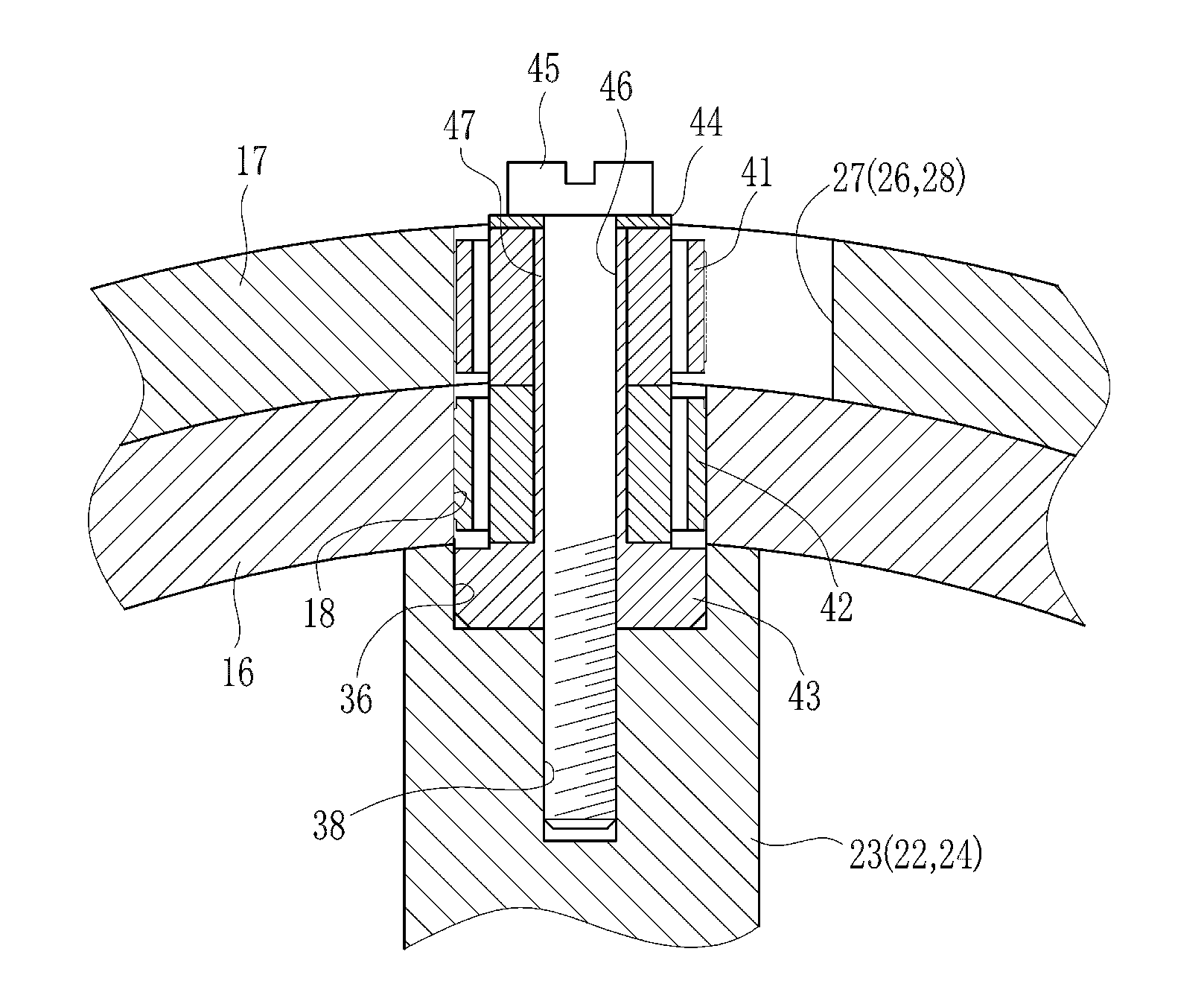
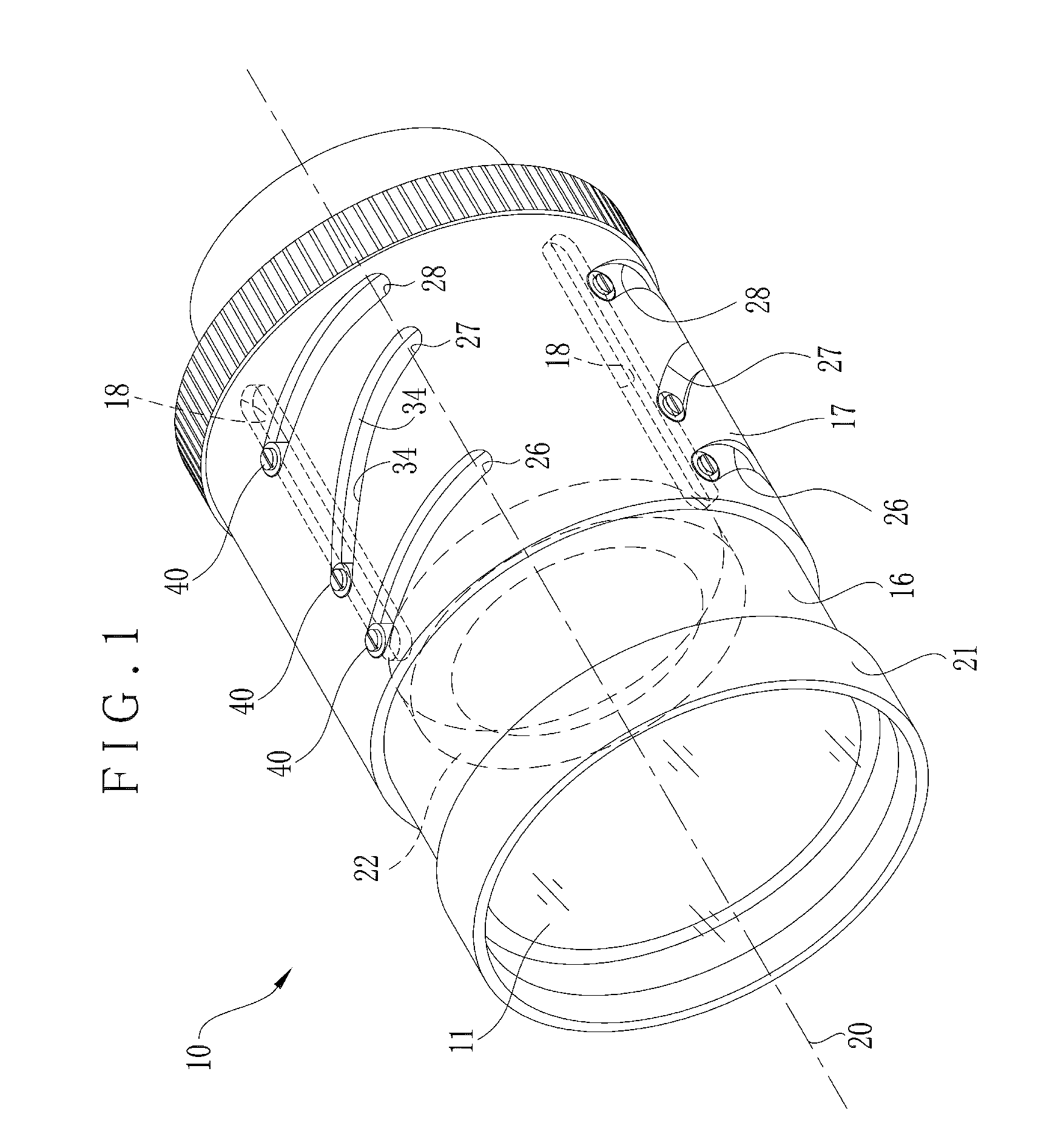
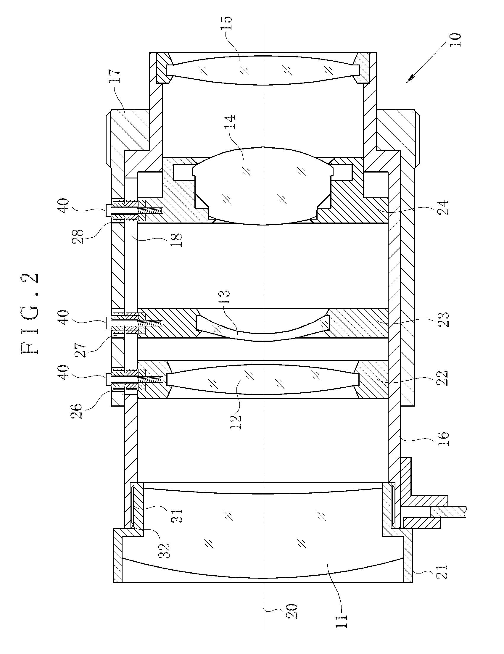
[0033]In FIGS. 1 and 2, a zoom lens apparatus 10 includes a lens system, a stationary barrel 16 for containing the lens system, and a cam barrel 17. The lens system includes a focusing lens component 11, magnification lens components 12, 13 and 14, and a rear lens component 15, each of which has one or more lens optics. A front lens holder 21 supports the focusing lens component 11. A male helical thread 31 is formed locally on a peripheral surface of the front lens holder 21. A female helical thread 32 is formed in the stationary barrel 16, and is engaged helically with the male helical thread 31. When the front lens holder 21 is rotated, the focus of the lens system is adjusted. Movable lens holders 22, 23 and 24 support respectively the magnification lens components 12-14. Three cam follower assemblies 40 of FIG. 3 are arranged on each of the peripheral surface of the movable lens holders 22-24. An optical axis 20 is defined in the lens system. The cam follower assemblies 40 are ...


PUM


Abstract

A zoom lens apparatus includes a movable magnification lens component, a stationary barrel, a movable lens holder, and a rotatable cam barrel. Plural cam grooves are formed in the cam barrel, have a pair of cam surfaces opposed to one another, for moving the movable lens holder in the optical axis direction by rotation of the cam barrel relative to the stationary barrel. Plural shaft devices are disposed on a peripheral surface of the movable lens holder, for extending in a radial direction being perpendicular to the optical axis direction. A cam follower device is secured to each of the shaft devices, and inserted in each of the cam grooves. A pair of cam follower surfaces are provided on the cam follower device, deformable resiliently about each of the shaft devices, and pressed by respectively the cam surfaces.

Description

BACKGROUND OF THE INVENTION[0001]1. Field of the Invention[0002]The present invention relates to a zoom lens apparatus having a movable lens holder. More particularly, the present invention relates to a zoom lens apparatus having a movable lens holder, in which a cam follower can be reliably kept engaged in a cam surface.[0003]2. Description Related to the Prior Art[0004]A zoom lens apparatus is widely used in combination with a camera, projector and other optical instruments. The zoom lens apparatus has a lens barrel and plural lens components. Relative positions of the lens components are changed to set the zoom lens apparatus at a desired zoom amount. Each of the lens components includes one or more lens optics and a lens holder for supporting the lens optics. One or more cam followers, for example three, are arranged on a peripheral surface of the lens holder. The zoom lens apparatus includes a stationary barrel and a cam barrel rotatable relative thereto. A linear groove is for...

Claims


Application Information

Patent Timeline
IPC IPC(8): G02B7/10
CPCG02B7/102G02B7/023
Inventor NAKAJIMA, KOJI
Owner FUJIFILM CORP
Why Eureka
Try Eureka