Method for smoothing a surface of a component

a technology for components and surfaces, applied in the direction of lapping machines, manufacturing tools, machines/engines, etc., can solve the problems of long processing time, unfavorable uniform removal, and added expens

Active Publication Date: 2020-08-13
MTU AERO ENGINES GMBH
View PDF4 Cites 2 Cited by
  • Summary
  • Abstract
  • Description
  • Claims
  • Application Information

AI Technical Summary

Benefits of technology

[0010]As already mentioned, the component can preferably involve a blade element or vane body of a turbomachine, this blade element or vane body being arranged in the gas channel thereof and subjected to flow. In principle, an application in the turbine region is also conceivable; the blade element or vane body thus can be arranged in the hot-gas channel and surrounded by the flow of hot

Problems solved by technology

Toward the trailing edge, however, it would decrease, which would result in an overall nonuniform removal.
Nevertheless, in order to achieve a certain homogenization, the compo

Method used


Image

  • Method for smoothing a surface of a component
  • Method for smoothing a surface of a component
  • Method for smoothing a surface of a component

Examples


Embodiment Construction

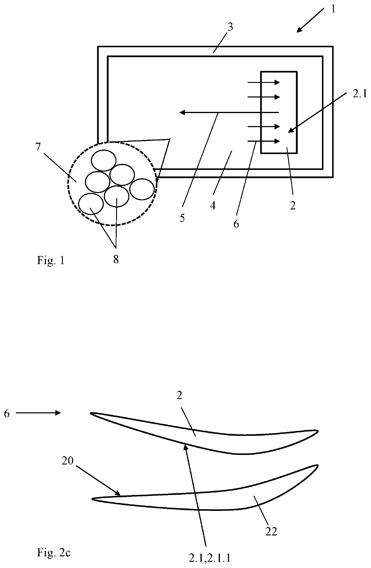
[0026]FIG. 1 shows a device 1 for smoothing a component 2, concretely a surface 2.1 of the component 2. Component 2 presently involves a blade or a blade element of an aircraft engine; see also FIG. 3 for illustration. For the smoothing, the component 2 is or will be placed in a container 3 that is filled with a liquid-solids mixture 4.

[0027]The component 2 then will be moved in the liquid-solids mixture 4, a relative movement 5 thus being produced between the liquid-solids mixture 4 and the component 2. In this way, a flow 6 of the liquid-solids mixture 4 is established along the surface 2.1 of the component 2. As the enlarged excerpt illustrates, the mixture 4 is made up of a liquid constituent 7 (presently, e.g., water, H2O2, silicates) and sphere-shaped solids 8 with a diameter of e.g., 0.5 mm. If the mixture 4, due to the relative movement 5, flows along the surface 2.1, the spheres roll out on the surface 2.1 with a certain pressure.

[0028]In order to obtain a more uniform pres...


PUM


Abstract

The present invention relates to a method for smoothing a surface of a component, in which a component is placed in a liquid-solids mixture; a relative movement is produced between the liquid-solids mixture and the component; thus there is a flow of the liquid-solids mixture along the surface; wherein there is provided in the liquid-solids mixture a guide surface, along which the liquid-solids mixture flows, wherein a directional component toward the surface is imposed on the flow.

Description

BACKGROUND OF THE INVENTION[0001]The present invention relates to a method for smoothing a component surface.[0002]Various methods are known for the smoothing of components: for example, a removal of material can be produced with a geometrically specific or nonspecific cutting by machining. Uneven places on the surface are removed with the removal of material; thus, the surface is smoothed, In the case of chemical-mechanical polishing, this smoothing can be produced by a combination of chemical and mechanical effects on the component surface. The present subject is directed toward such a method, wherein it particularly concerns the smoothing of components of turbomachines or engines.[0003]A turbomachine can be functionally divided into compressor, combustion chamber and turbine, wherein, in the case of an aircraft engine, aspirated air is compressed in the compressor and is combusted in the downstream combustion chamber with kerosene mixed in. The hot gas that arises, a mixture of c...

Claims


Application Information

Patent Timeline
IPC IPC(8): B24B31/12B24B37/02B24B31/00B24B31/14F01D5/14F01D9/02
CPCB24B31/12B24B31/14B24B31/003F05D2230/10B24B37/02F01D9/02F01D5/14B24B31/116B24B19/14
Inventor FESSLER-KNOBEL, MARTINWINDPRECHTINGER, JOERGASTL, GEORG
Owner MTU AERO ENGINES GMBH
Why Eureka
Try Eureka