Supercharge Your Innovation With Domain-Expert AI Agents!

Casing for electronic ballast

a technology of electronic ballast and casing, which is applied in the field of electronic ballast, can solve the problems of increasing the cost of the overall product, wasting time and labor, and reducing the overall product cost, so as to simplify the assembly and reduce the cos

Active Publication Date: 2012-01-05
ABL IP HLDG
View PDF4 Cites 2 Cited by
  • Summary
  • Abstract
  • Description
  • Claims
  • Application Information

AI Technical Summary

Benefits of technology

The invention provides a one-piece casing for electronic ballast that is simple and lower in cost. The casing has a top wall, bottom wall, side walls, and end walls that are formed integrally. The end walls are pivotable to close the opening formed by the top wall, bottom wall, and side walls. The inner surface of the side walls has a support portion for supporting the plate body of the PCB assembly. The end wall also has a body extending from the top wall and a second holding portion for positioning the PCB assembly inside the casing. The invention simplifies the assembly and lowers the cost of electronic ballast assembly compared to conventional two-piece or multi-piece casing configurations.

Problems solved by technology

Nevertheless, the casing for electronic ballast from prior art is assembled by a plurality of components and is structurally complicated as well as costly in manufacturing.
Thus, it takes too much time to assemble the casing and electronic components, thereby further increasing the cost of the overall product.

Method used


Image

  • Casing for electronic ballast
  • Casing for electronic ballast
  • Casing for electronic ballast

Examples


Embodiment Construction

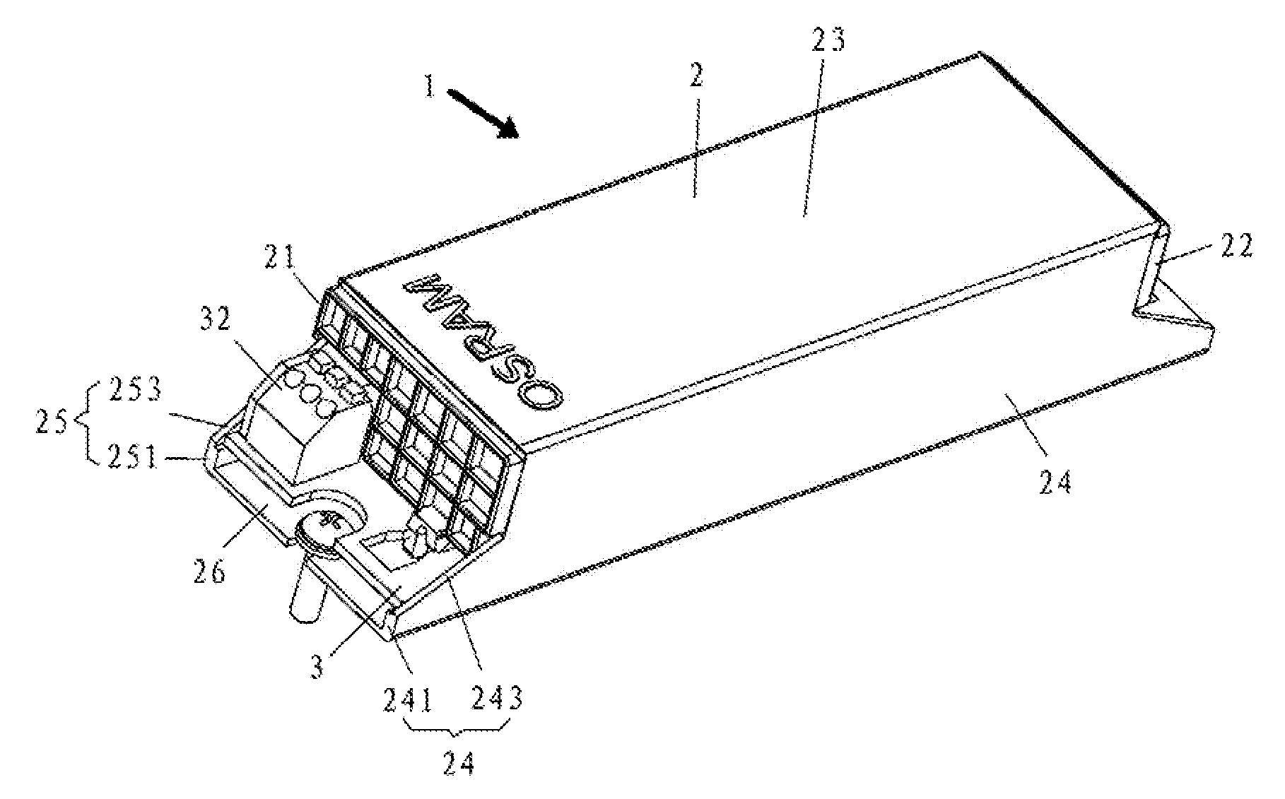
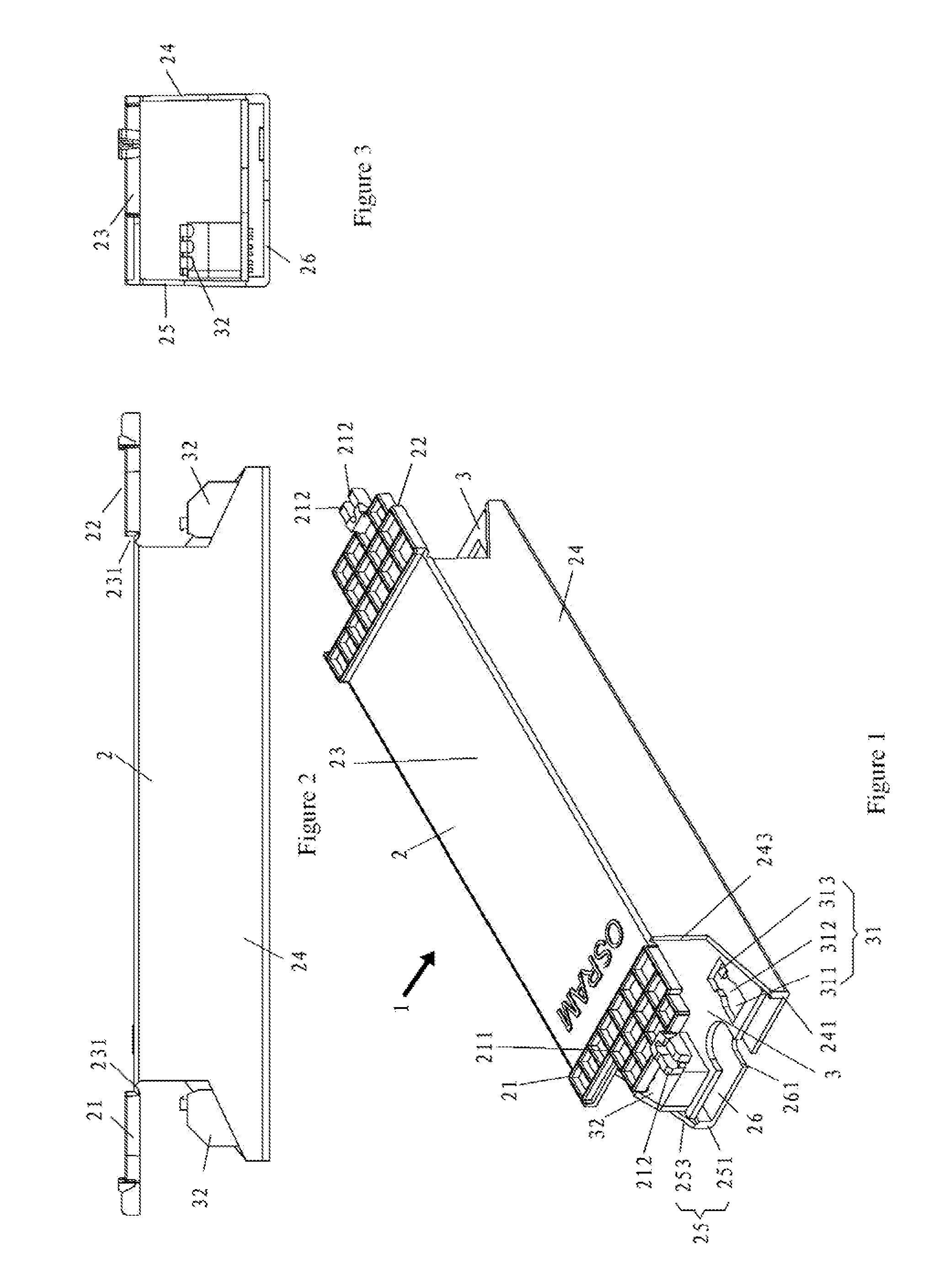
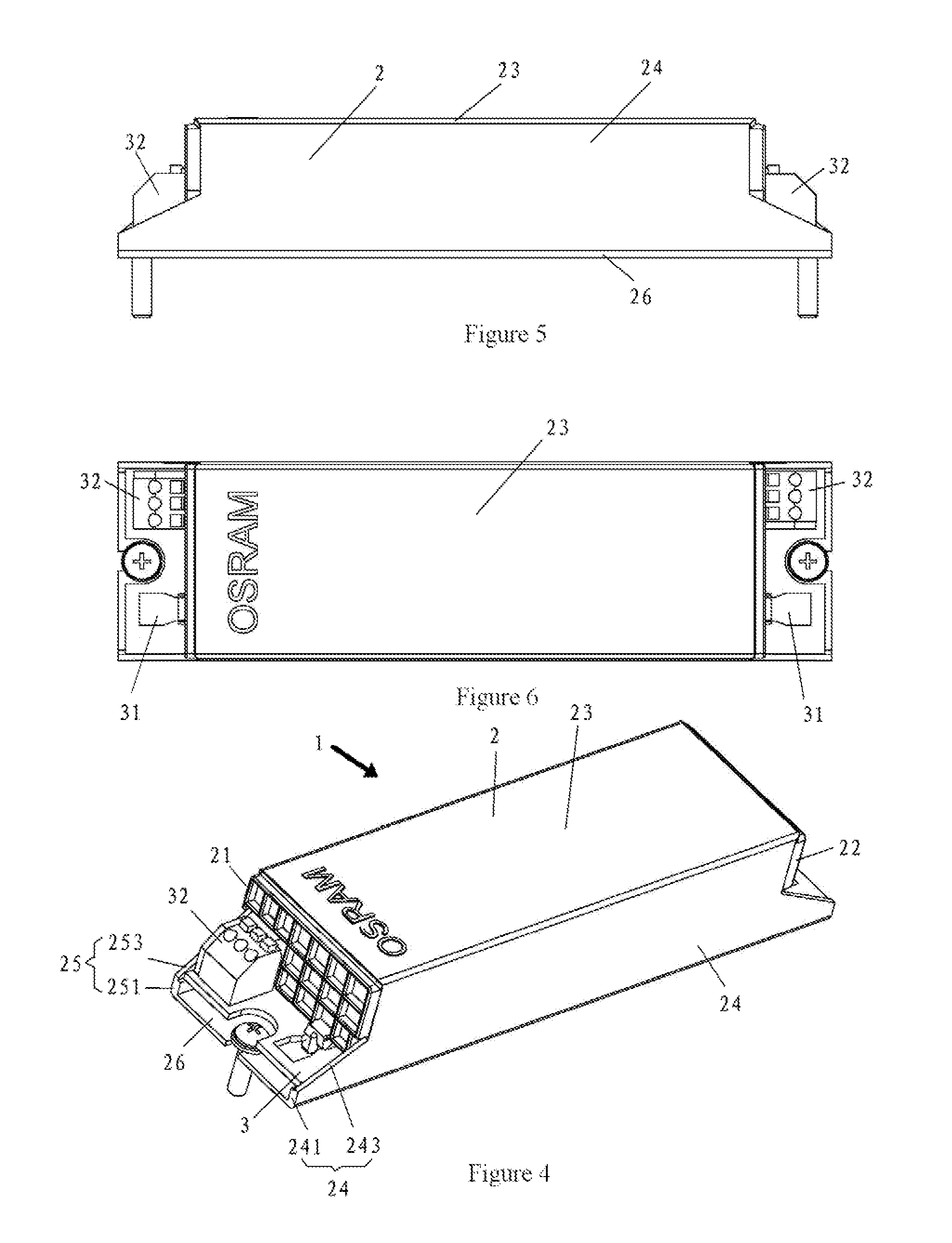
[0016]As shown in FIG. 1, an electronic ballast assembly according to an embodiment of the invention is designated at 1 in its entirety. The electronic ballast assembly 1 comprises a PCB assembly 3 and a casing 2 for receiving the PCB assembly 3.

[0017]With reference to FIG. 1, in the illustrated embodiment, the PCB assembly 3 comprises a plate-shaped plate body 33, a terminal 32 disposed at the opposite ends of the plate body 33 for wire connecting and disconnecting, and a first holding portion disposed at the opposite ends of the plate body 33 for enabling the positioning of the PCB assembly 3 inside the casing 2. In the present embodiment, the first holding portion is a notch 31 composed of a first notch portion 311, a second notch portion 312 and a third notch portion 313 that are sequentially disposed in the lengthwise direction of the PCB assembly 3 near the end of the PCB assembly 3, wherein the width of the first notch portion 311 and the width of the third notch portion 313 ...


PUM

PropertyMeasurementUnit
thicknessaaaaaaaaaa
widthaaaaaaaaaa
lengthaaaaaaaaaa

Abstract

A casing for electronic ballast, in which a PCB assembly is received, may include: a top wall; a bottom wall opposite to the top wall; two opposite side walls extending integrally between the top wall and bottom wall; and two opposite end walls extending integrally from the top wall, wherein the top wall, bottom wall, side walls and end walls are formed integrally, the top wall, bottom wall and side walls define openings at both ends of the casing in a lengthwise direction of the casing, the end walls are arranged to be pivotable relative to the top wall so as to close the openings formed by the top wall, bottom wall and side walls.

Description

FIELD OF INVENTION[0001]The invention relates to an electronic ballast, in particular, to a one-piece low cost casing for electronic ballast. Further, the invention relates to an electronic ballast assembly and a method of assembling the same.BACKGROUND ART[0002]An electronic ballast is a commonly used electronic component and is widely used in the illumination field. A whole electronic ballast comprises an input rectifier module, a power factor calibrating module and a DC / AC inverter. Thus, an electronic ballast must be packed into suitable sizes to enable the use of conventional electronic ballast in household.[0003]Chinese Utility Model No. 01256696.9 discloses a casing for electronic ballast adapted to be used in outdoors illumination devices. The middle of the case for electronic ballast is designed to be a hollow metal casing. The both ends of the casing are designed to be socket-connected with a polymer casing made with a mould. The polymer casing fits the caliber of the meta...

Claims


Application Information

Patent Timeline
Patent Type & Authority Applications(United States)
IPC IPC(8): H05K5/02H05K3/00
CPCH05B41/02H05K5/0013Y10T29/49124F21V23/026H05K5/0026
Inventor TISO, MICHELETWARDZIK, RENEXIE, FUBING
Owner ABL IP HLDG
Features
  • R&D
  • Intellectual Property
  • Life Sciences
  • Materials
  • Tech Scout
  • Unparalleled Data Quality
  • Higher Quality Content
  • 60% Fewer Hallucinations
Learn More