Designing method for dimple pattern of golf ball

a golf ball and dimple pattern technology, applied in the field of golf balls, can solve the problems of affecting the aerodynamic symmetry of the golf ball, unable to obtain sufficient dimple effect, and difficult to remove the flash generated inside the dimple, so as to reduce the distance between two adjacent dimples

Inactive Publication Date: 2012-01-05
SUMITOMO RUBBER IND LTD
View PDF21 Cites 24 Cited by
  • Summary
  • Abstract
  • Description
  • Claims
  • Application Information

AI Technical Summary

Benefits of technology

[0023](4-1) correcting a position of a dimple in the vicinity of a boundary betwee

Problems solved by technology

Removal of a flash generated inside the dimple is difficult.
Thus, a sufficient dimple effect is not obtained.
The difference between these dimple effects impairs the aerodynamic symmetry of a golf ball.
Other than a shot at a teeing ground, golf players cannot decide a hitting place of a golf ball.
Golf players have difficulty in landing this golf ball at an intended point.
The flight distance o

Method used


Image

  • Designing method for dimple pattern of golf ball
  • Designing method for dimple pattern of golf ball
  • Designing method for dimple pattern of golf ball

Examples


embodiment 1

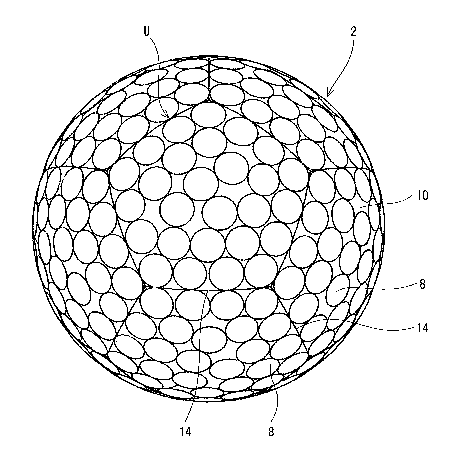
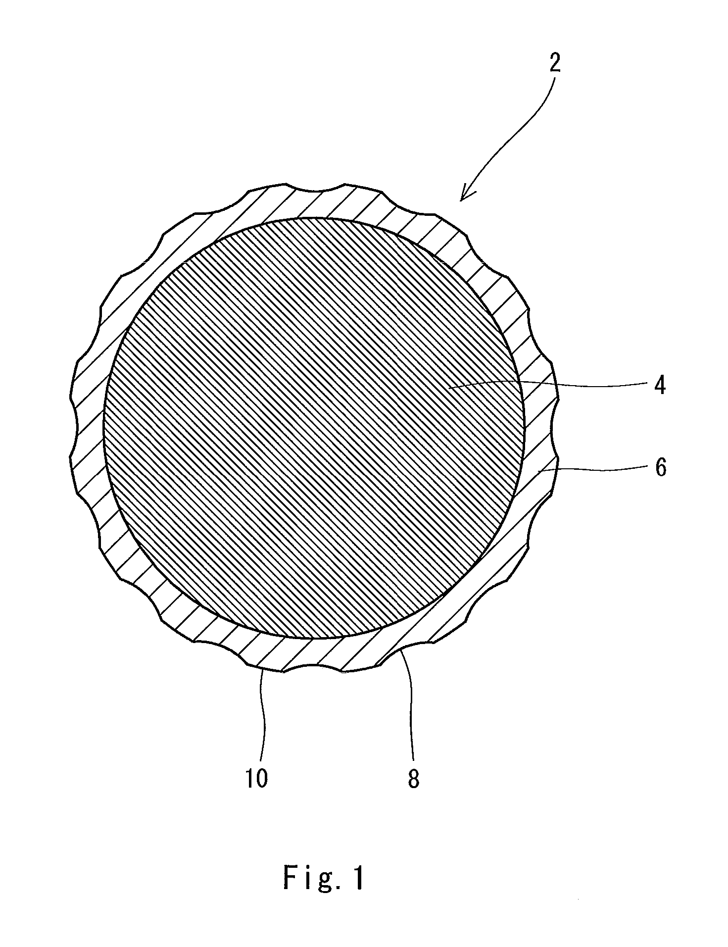
[0071]A golf ball 2 shown in FIG. 1 includes a spherical core 4 and a cover 6. On the surface of the cover 6, a large number of dimples 8 are formed. Of the surface of the golf ball 2, a part other than the dimples 8 is a land 10. The golf ball 2 includes a paint layer and a mark layer on the external side of the cover 6 although these layers are not shown in the drawing. A mid layer may be provided between the core 4 and the cover 6.

[0072]The golf ball 2 has a diameter of 40 mm or greater but 45 mm or less. From the standpoint of conformity to the rules established by the United States Golf Association (USGA), the diameter is more preferably equal to or greater than 42.67 mm. In light of suppression of air resistance, the diameter is more preferably equal to or less than 44 mm and particularly preferably equal to or less than 42.80 mm. The golf ball 2 has a weight of 40 g or greater but 50 g or less. In light of attainment of great inertia, the weight is more preferably equal to or...

embodiment 2

[0113]FIG. 15 is a front view of a golf ball 18 according to another embodiment of the present invention. FIG. 16 is a plan view of the golf ball 18 in FIG. 15. FIGS. 15 and 16 show some of division lines 14 obtained by projecting the edge lines of the regular icosahedron inscribed in a phantom sphere, on the surface of the phantom sphere. The rest of the division lines is not shown in FIGS. 15 and 16.

[0114]By projecting the edge lines of the regular icosahedron on the surface of the phantom sphere, 20 spherical regular triangles are obtained. In the embodiment, one unit is assumed by combining two adjacent spherical regular triangles. The number of units is 10. FIG. 17 shows one unit U. The unit U is a combination of a first spherical regular triangle 20 and a second spherical regular triangle 22. One spherical regular triangle may be one unit U.

[0115]FIG. 17 shows a base pattern. In the base pattern, a plurality of dimples is randomly arranged in the unit U such that the dimples d...

embodiment 3

[0123]FIGS. 20 and 21 show a dimple pattern of a golf ball 30 according to Embodiment 3. FIGS. 20 and 21 show division lines obtained by projecting the edge lines of the regular dodecahedron inscribed in a phantom sphere, on the surface of the phantom sphere. In the actual golf ball 30, the division lines 14 are not viewed. By these division lines 14, the surface of the phantom sphere is divided into 12 units U. The procedure of this division is the same as that of the golf ball 2 according to Embodiment 1.

[0124]The base pattern of the golf ball 30 is the same as the base pattern according to Embodiment 1 shown in FIG. 5. In the golf ball 30, the pattern of one unit U and the pattern of the other unit U are not mirror-symmetrical to each other in all pairs of adjacent units. The ratio Pn of the golf ball 30 is 100%.

Evaluation

[0125]The aerodynamic symmetries of golf balls according to Embodiments 1 to 3 and Comparative Examples 1 and 2 are evaluated. Prior to the evaluation, the spec...


PUM


Abstract

A designing method according to the present invention includes the steps of:
(1) dividing a surface of a phantom sphere of a golf ball 2 into a plurality of units U by division lines 14 obtained by projecting edge lines of a regular polyhedron inscribed in the phantom sphere, on the surface of the phantom sphere;
(2) obtaining a base pattern by randomly arranging a plurality of dimples 8 in one unit U such that the dimples 8 do not overlap each other; and
(3) developing the base pattern over other units U such that patterns of two adjacent units U are not mirror-symmetrical to each other. The regular polyhedron is preferably a regular dodecahedron or a regular icosahedrons.

Description

[0001]This application claims priority on Patent Application No. 2010-148473 filed in JAPAN on Jun. 30, 2010. The entire contents of this Japanese Patent Application are hereby incorporated by reference.BACKGROUND OF THE INVENTION[0002]1. Field of the Invention[0003]The present invention relates to golf balls. Specifically, the present invention relates to designing methods for dimple patterns of golf balls.[0004]2. Description of the Related Art[0005]Golf balls have a large number of dimples on the surface thereof. The dimples disturb the air flow around the golf ball during flight to cause turbulent flow separation. By causing the turbulent flow separation, separation points of the air from the golf ball shift backwards leading to a reduction of drag. The turbulent flow separation promotes the displacement between the separation point on the upper side and the separation point on the lower side of the golfball, which results from the backspin, thereby enhancing the lift force that...

Claims


Application Information

Patent Timeline
IPC IPC(8): A63B37/14A63B37/00
CPCA63B37/0006A63B37/00065
Inventor KIM, HYOUNGCHOL
Owner SUMITOMO RUBBER IND LTD
Why Eureka
Try Eureka