Downhole corrosion monitoring

Inactive Publication Date: 2012-01-12
SCHLUMBERGER TECH CORP
View PDF27 Cites 19 Cited by
  • Summary
  • Abstract
  • Description
  • Claims
  • Application Information

AI Technical Summary

Problems solved by technology

As such, downhole tools may be exposed to increasingly hostile environments, such as by having increased downhole pressure, temperature, increased level of shock and vibration, in addition to increasingly corrosive environments.
For example, as the corrosivity of downhole environments increases, the useful life of the downhole tools in these environm

Method used


Image

  • Downhole corrosion monitoring
  • Downhole corrosion monitoring
  • Downhole corrosion monitoring

Examples


Embodiment Construction

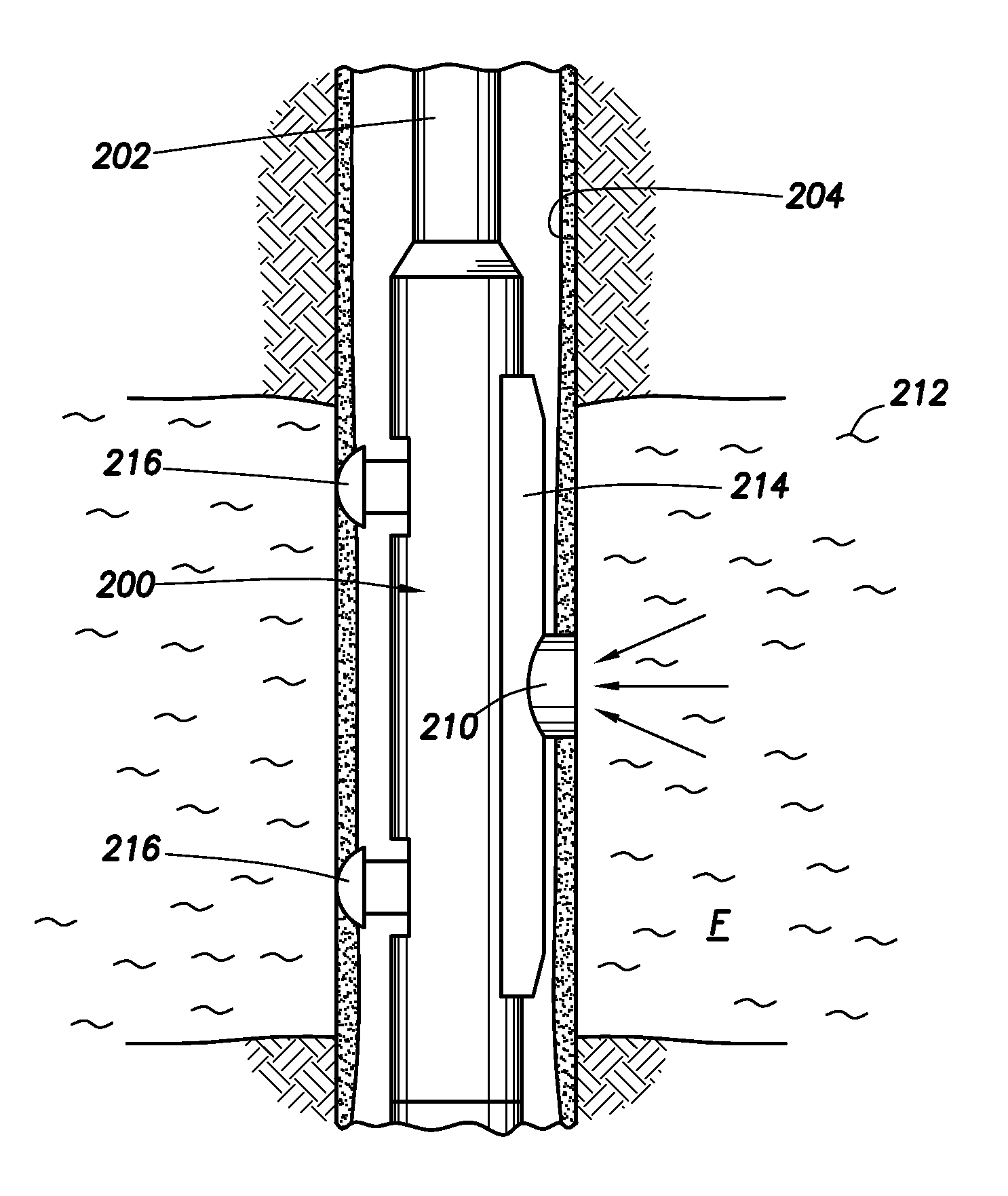
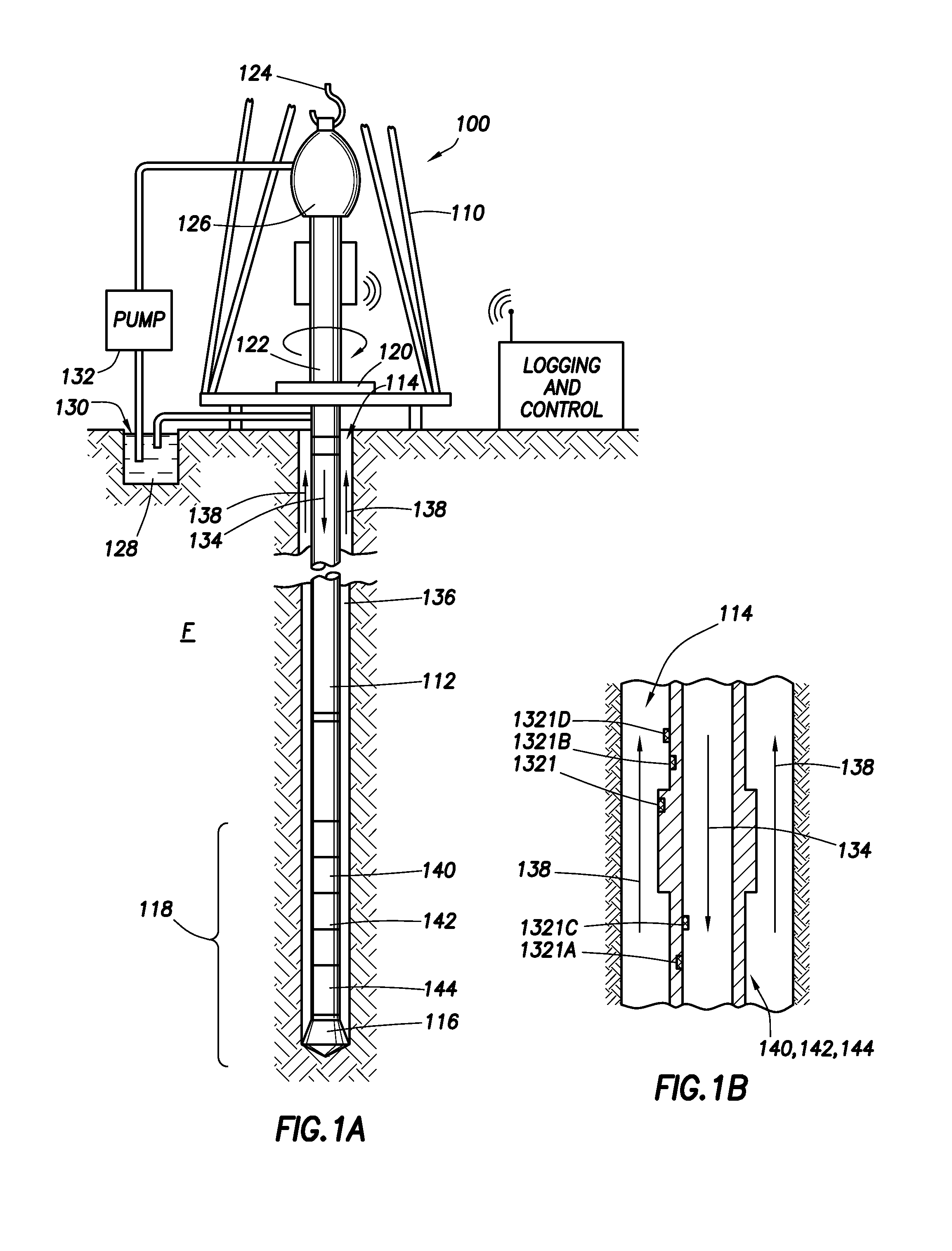
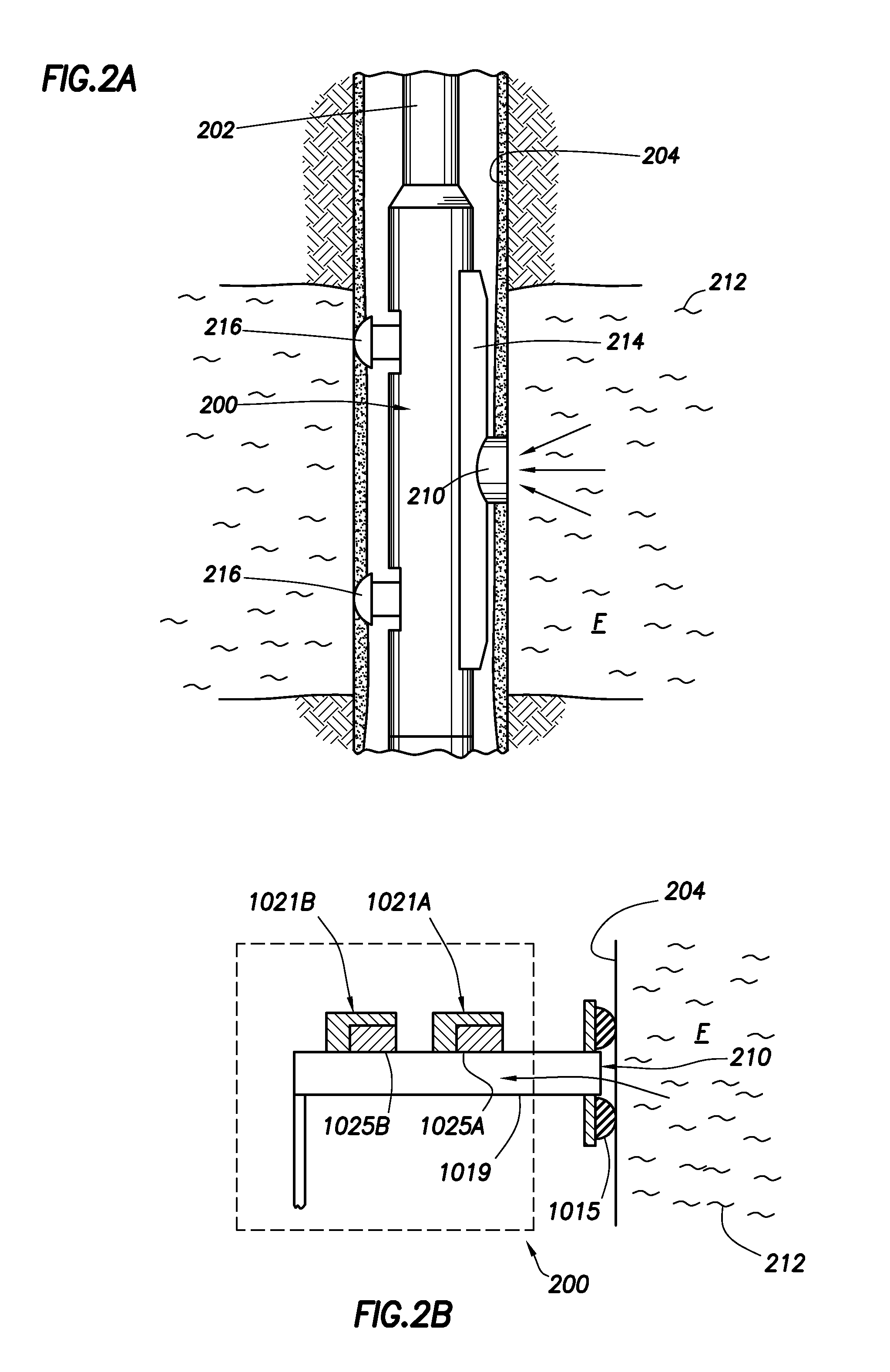
[0019]It is to be understood that the following disclosure provides many different embodiments, or examples, for implementing different features of various embodiments. Specific examples of components and arrangements are described below to simplify the present disclosure. These are, of course, merely examples and are not intended to be limiting. In addition, the present disclosure may repeat reference numerals and / or letters in the various examples. This repetition is for the purpose of simplicity and clarity and does not in itself dictate a relationship between the various embodiments and / or configurations discussed. Moreover, the subterranean formation of a first feature over or on a second feature in the description that follows may include embodiments in which the first and second features are formed in direct contact, and may also include embodiments in which additional features may be formed interposing the first and second features, such that the first and second features ma...


PUM


Abstract

Apparatus and methods for measuring an effect of corrosion with a corrosion sensor. The apparatus includes at least a portion of a metal material configured to be disposed within a borehole and exposed to a fluid. The apparatus includes a sensor configured to measure an effect of corrosion of the at least portion of the metal material within the fluid.

Description

BACKGROUND OF THE DISCLOSURE [0001]Wells are generally drilled into the ground or ocean bed to recover natural deposits of oil and gas, as well as other desirable materials that are trapped in geological formations in the Earth's crust. Wells are typically drilled using a drill bit attached to the lower end of a “drill string.” Drilling fluid, or mud, is typically pumped down through the drill string to the drill bit. The drilling fluid lubricates and cools the bit, and may additionally carry drill cuttings from the borehole back to the surface.[0002]In various oil and gas exploration operations, it may be beneficial to have information about the fluids contained in the subterranean formations that are penetrated by a borehole. For example, certain formation evaluation schemes include measurement and analysis of the fluids extracted from the subterranean formations. These measurements may be essential to designing the production facility and predicting the lifetime thereof.[0003]Res...

Claims


Application Information

Patent Timeline
IPC IPC(8): G01R27/08
CPCG01N17/02
Inventor FISSELER, PATRICK J.GOODWIN, ANTHONY R.H.CAMPANAC, PIERRESTILL, JOHN W.
Owner SCHLUMBERGER TECH CORP
Why Eureka
Try Eureka