
Periodic correlated magnetic actuator systems and methods of use thereof

a magnetic actuator and correlated technology, applied in the field of electromagnetical motors, can solve the problems of limited utilization of permanent magnetic energy and elusive use of permanent magnetic energy stored in the field of permanent magnets to produce mechanical energy, and achieve the effect of reducing the distance required and therefore the tim

Inactive Publication Date: 2012-01-12
NANO CARBON FOOTPRINT
View PDF13 Cites 27 Cited by
  • Summary
  • Abstract
  • Description
  • Claims
  • Application Information

AI Technical Summary

Benefits of technology

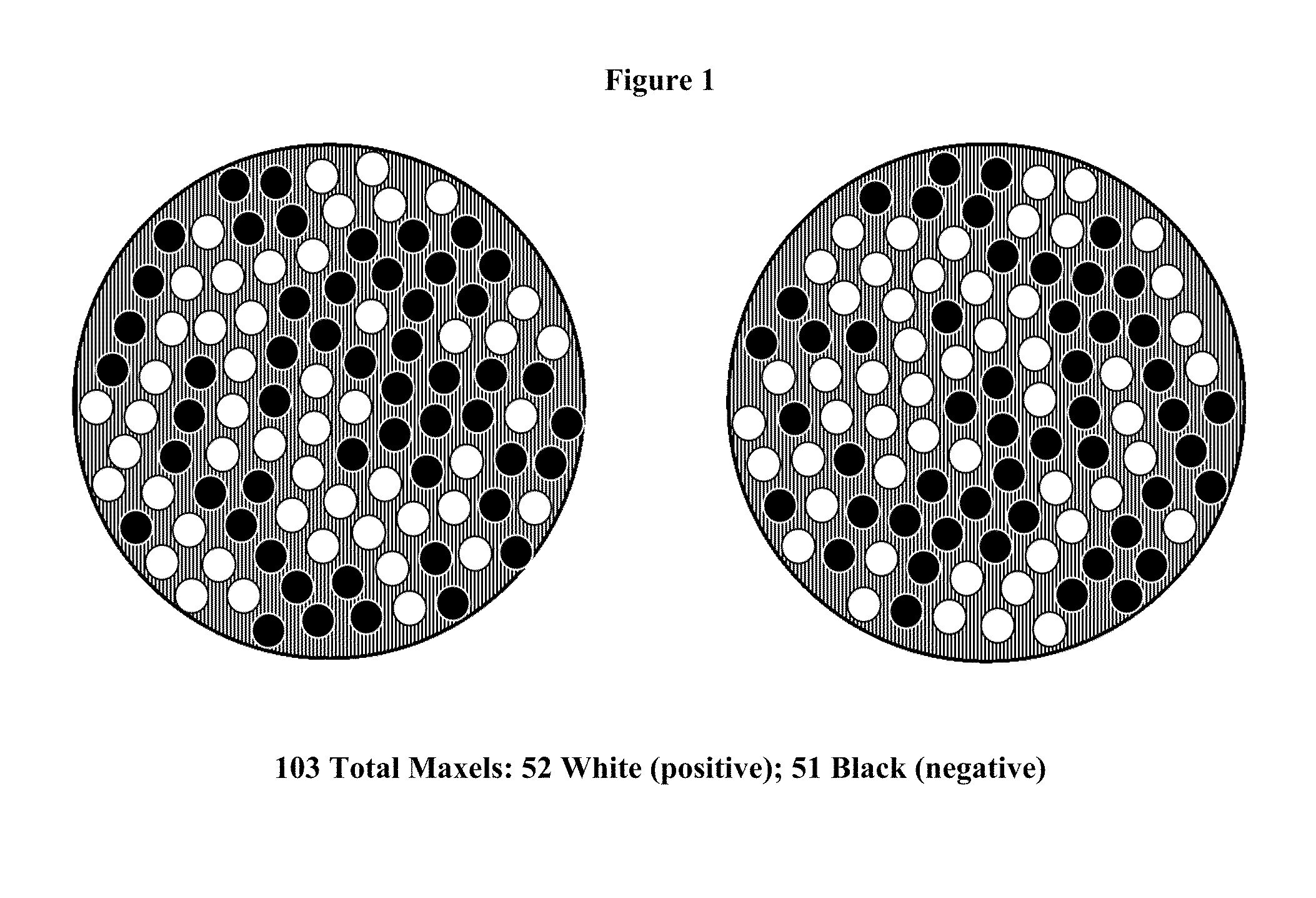
[0006]In one exemplary embodiment, the coding of the correlated magnets is configured so that binary spatial manipulation produces a strong, or peak, mutual coupling force in only one spatial orientation. In another exemplary embodiment, the coding of the correlated magnet is configured so that binary spatial manipulation produces a strong, or peak, mutual coupling force in more than one spatial orientation. In yet another exemplary embodiment, the correlated actuation magnet coding of a tier is further configured so that the binary spatial manipulation force required to couple and decouple the strong, or peak, mutual force is minimized. In another exemplary embodiment, the correlated actuation magnet coding is configured so that the binary spatial manipulation minimizes the distance required, and therefore the time required, to actuate, translate, couple, and decouple the strong, or peak, mutual force of a tier.

Problems solved by technology

However, the use of permanent magnetic energy stored in the fields of permanent magnets to produce mechanical energy has been elusive.
The utilization of permanent magnetic energy is limited in that the work required to separate (negative system work burden) a previously attracted pair of magnets would always be greater than the work produced (positive system work) during the original dynamic attraction of a magnet pair.
The net difference between the negative work required and positive work produced results in a net negative value and therefore rendered such topologies irrelevant due to inability to produce positive net work output.

Method used


Image

  • Periodic correlated magnetic actuator systems and methods of use thereof
  • Periodic correlated magnetic actuator systems and methods of use thereof
  • Periodic correlated magnetic actuator systems and methods of use thereof

Examples


Embodiment Construction

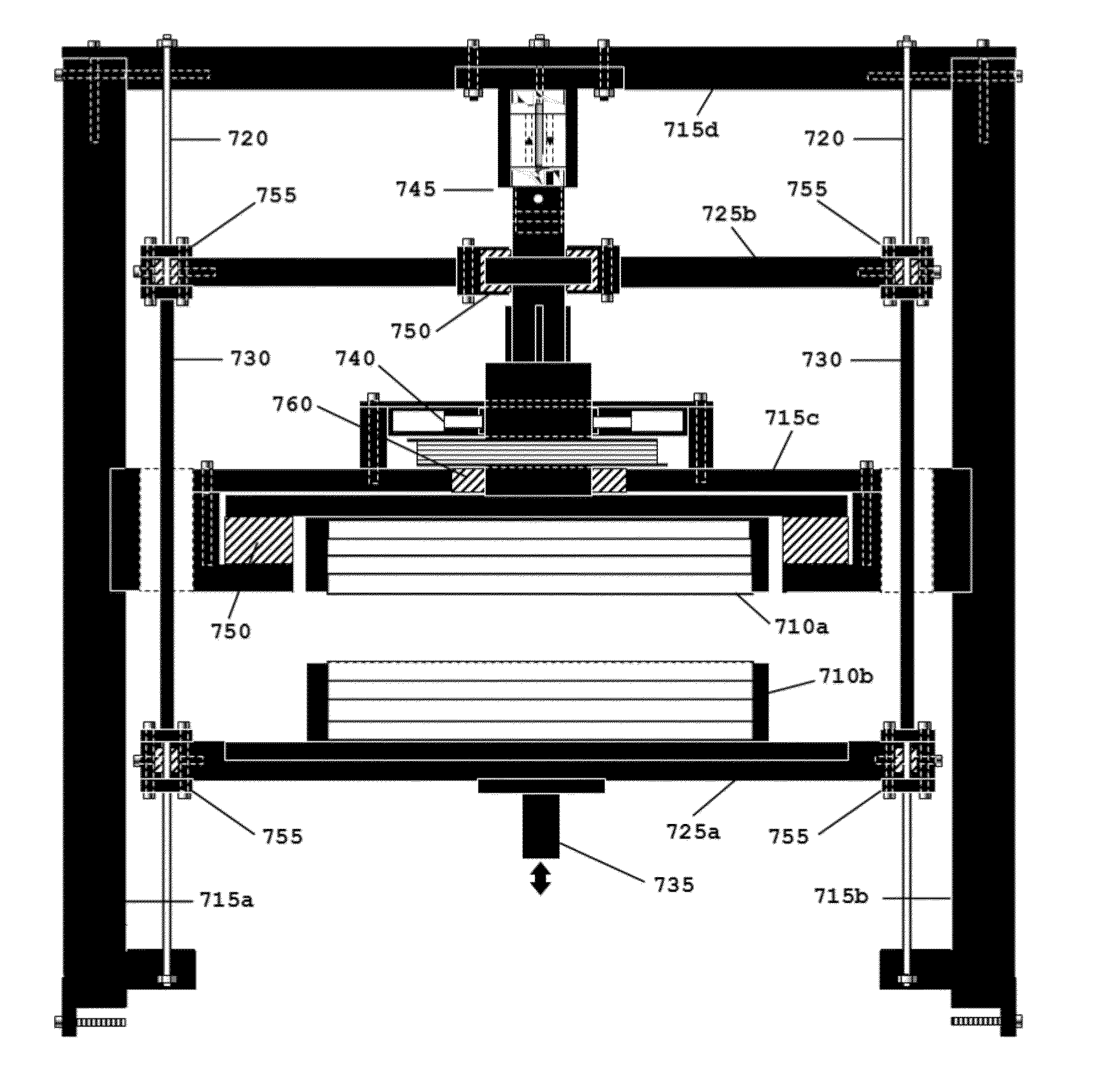
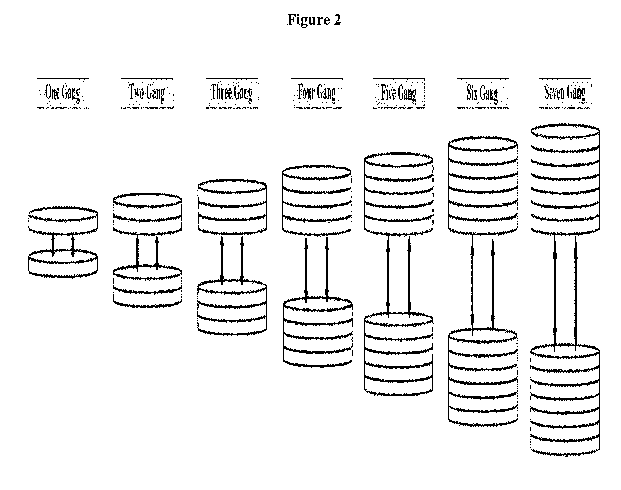
[0033]The present invention comprises correlated magnet actuators, devices incorporating said actuators, and methods of use thereof. The actuators utilize magnetic drives comprising a pair of complimentary correlated permanent magnet pairs, arranged in a separable and opposing fashion. The attractive or repulsive force of each correlated magnet pair drops significantly after only a few degrees of rotation off of a prime attractive or repulsive rotational alignment, allowing the magnets to be binarily manipulated between a correlated and decorrelated alignment. The linear motion resulting from the periodic coupling and decoupling of the magnetic pair can be translated to supporting conveyance structures to produce rotary (torque) output work. This output work can be harnessed to drive secondary utilization components such as a generator or a pump, or other devices dependent on rotary work output for their operation.

Correlated Magnets

[0034]A “correlated permanent magnet” as used herei...


PUM


Abstract

The present invention comprises correlated magnet actuators, devices incorporating said actuators, and methods of use thereof. The actuators utilize magnetic drives comprising a pair of complimentary correlated permanent magnet pairs, arranged in a separable and opposing fashion. The attractive or repulsive force of each correlated magnet pair drops significantly after only a few degrees of rotation off of a prime attractive or repulsive rotational alignment, allowing the magnets to be binarily manipulated between a correlated and decorrelated alignment. The linear motion resulting from the periodic coupling and decoupling of the magnetic pair can be translated to supporting conveyance structures to produce rotary (torque) output work. This output work can be harnessed to drive secondary utilization components such as a generator or a pump, or other devices dependent on rotary work output for their operation.

Description

CROSS REFERENCE TO RELATED APPLICATIONS[0001]This application claims the benefit of U.S. Provisional Patent Application No. 61 / 362,585 filed Jul. 8, 2010.FIELD OF THE INVENTION[0002]The present invention is directed to electromagnetic motors. Specifically, the present invention is directed to permanent magnetic actuators and methods of use thereof. More specifically the present invention is directed to the binary spatial manipulation of correlated magnetic drives to translate permanent magnetic force into useful rotary work output.BACKGROUND OF THE INVENTION[0003]Electromagnetic motors are found in applications as diverse as industrial fans, blowers and pumps, machine tools, household appliances, power tools, and disk drives. Most electromagnetic motors produce rotary (torque) work by converting electrical energy into mechanical energy (torque). Existing electromagnetic motors operate on the principle that a conductor carrying a current in a magnetic field tends to move perpendicula...

Claims


Application Information

Patent Timeline
IPC IPC(8): H01F7/02
CPCH01F7/0242H02K49/102H02K49/10H02K41/06
Inventor NERL, MICHAEL S.
Owner NANO CARBON FOOTPRINT
Learn More