
Control device and control method for four-wheel drive vehicle

a four-wheel drive, control device technology, applied in the direction of braking systems, instruments, analogue processes for specific applications, etc., can solve the problems of affecting the durability of the front dss, the durability of the drive train may possibly further deteriorate, and the durability of the drive train may be considerably deteriorated. , to achieve the effect of reducing the twisting torque and improving the durability of the components of the drive train

Inactive Publication Date: 2012-01-12
TOYOTA JIDOSHA KK
View PDF20 Cites 7 Cited by
  • Summary
  • Abstract
  • Description
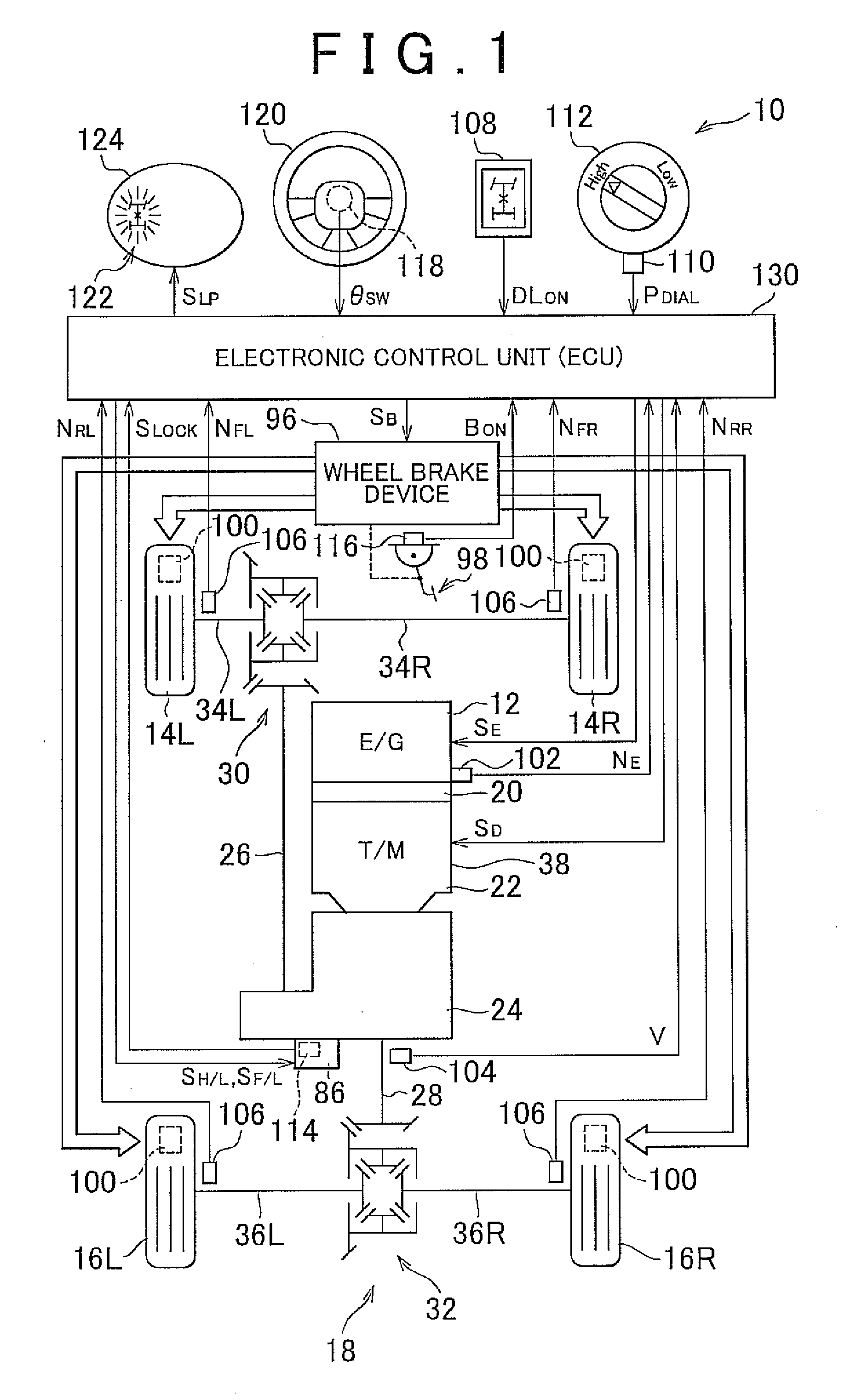
  • Claims
  • Application Information

AI Technical Summary

Benefits of technology

[0007]The invention provides a control device and control method for a four-wheel drive vehicle, which are able to improve the durability of components of a drive train by reducing a twisting torque applied to the drive train.
[0009]By so doing, when the drive train is placed in the twisted state where the twisting torque resulting from the twist accumulated in the drive train is larger than or equal to the predetermined torque during cornering in the non-differential mode, braking force is applied to the front wheels by the wheel brake device. Therefore, for example, part of a negative torque (decelerating torque) that acts on the front wheels may be cancelled by the braking torque applied by the wheel brake device, so the twisting torque that is substantially applied to the drive train is reduced. That is, part of a generated twisting torque is cancelled by the braking torque, so the twisting torque that acts on the drive train components is reduced. Thus, the durability of the drive train components is improved. Therefore, for example, it is not necessary to increase the size of the drive train components in order to ensure the durability of the drive train components, and it is possible to reduce the size and weight of the drive train components.
[0010]In the control device, the predetermined torque may be reduced as a steering angle during the cornering increases. In addition, the predetermined torque may be an allowable value of the twisting torque for suppressing deterioration of durability of drive train components, and may be set on the basis of an actual steering angle from a predetermined correlation. By so doing, for example, in contrast to a decrease in allowable torque of the drive train components (for example, front DSs) against a twisting torque as the steering angle increases, the predetermined torque is set from the above correlation, so the twisting torque that acts on the drive train components is appropriately reduced to thereby improve the durability of the drive train components. In addition, braking torque is applied by the wheel brake device in accordance with a steering angle, so turning performance (travelling performance) is appropriately ensured. That is, for example, part of a decelerating torque that acts on the front wheels is appropriately cancelled by the braking torque applied by the wheel brake device, so a decelerating torque of the vehicle overall is not increased by the braking torque, and travelling performance is appropriately ensured.

Problems solved by technology

A torque at which at least one of the wheels starts to slip (hereinafter, referred to as tractive torque) is relatively large, so the durability of portions that constitute the drive train may possibly deteriorate.
Particularly, when the weight of a vehicle is relatively heavy or when the vehicle total weight is relatively heavy, a tractive torque increases (that is, the wheels are hard to start slipping), so a larger twisting torque accumulates and, as a result, the durability of the portions of the drive train may possibly further deteriorate.
In addition, when the vehicle is cornering, wheel-side joints of the front DSs are turned at a large angle, and the durability of the front DSs may considerably deteriorate as compared with when the vehicle is travelling straight ahead.

Method used


Image

  • Control device and control method for four-wheel drive vehicle
  • Control device and control method for four-wheel drive vehicle
  • Control device and control method for four-wheel drive vehicle

Examples


Embodiment Construction

[0025]In an embodiment of the invention, a four-wheel drive vehicle is, for example, a so-called full-time four-wheel drive vehicle in which power of a driving force source is distributed between a front wheel-side power transmission path and a rear wheel-side power transmission path via a center differential (center diff) that is alternatively changeable between a free mode and a locked mode. When the center diff is changed from the free mode to the locked mode (center diff locked mode), the four-wheel drive vehicle is able to travel in a non-differential mode where differential rotation between front wheels and rear wheels is limited.

[0026]In addition, the four-wheel drive vehicle may be, for example, a so-called part-time four-wheel drive vehicle in which the center diff is replaced with a lock mechanism, instead of the full-time four-wheel drive vehicle. The four-wheel drive vehicle travels in a two-wheel drive mode when the lock mechanism is set in the free mode; whereas, when ...


PUM


Abstract

In a control for a four-wheel drive vehicle that is able to travel in a non-differential mode in which differential rotation between front wheels and rear wheels is limited, it is determined whether a drive train is placed in a twisted state where a twisting torque resulting from a twist accumulated in the drive train is larger than or equal to a predetermined torque while the vehicle is cornering in the non-differential mode, and braking force is applied to the front wheels by a wheel brake device when it is determined that the drive train is placed in the twisted state.

Description

INCORPORATION BY REFERENCE[0001]This application claims priority of Japanese Patent Application No. 2010-157193 filed on Jul. 9, 2010, which is incorporated herein by reference in its entirety including the specification, drawings and abstract.BACKGROUND OF THE INVENTION[0002]1. Field of the Invention[0003]The invention relates to a control device and control method for a four-wheel drive vehicle that is able to travel in a non-differential mode of front and rear wheels.[0004]2. Description of Related Art[0005]There is widely known a four-wheel drive vehicle that is able to travel in a non-differential mode in which differential rotation between front wheels and rear wheels is limited. For example, Japanese Patent Application Publication No. 2008-143380 (JP-A-2008-143380) and Japanese Patent Application Publication No. 2000-344077 (JP-A-2000-344077) describe such a vehicle. For example, JP-A-2008-143380 describes that, in a full-time four-wheel drive vehicle in which the power of an...

Claims


Application Information

Patent Timeline
Patent Type & Authority Applications(United States)
IPC IPC(8): G06F19/00
CPCB60K23/0808B60W10/184B60W30/18145B60T2201/14B60W2540/18B60T8/1769B60W2510/202
Inventor ITO, KOHEI
Owner TOYOTA JIDOSHA KK
Learn More