Coaxial valve with an electric drive

a technology of electric drive and coaxial valve, which is applied in the direction of valve details, valve arrangement, operating means/releasing devices, etc., can solve the problem of being unsusceptible to engine vibration, and achieve the effect of increasing the external seal and minimising leakag

Active Publication Date: 2012-01-19
ARIANEGRP GMBH
View PDF4 Cites 13 Cited by
  • Summary
  • Abstract
  • Description
  • Claims
  • Application Information

AI Technical Summary

Benefits of technology

[0026]In a further embodiment of the coaxial valve, the secondary leakage paths on the plain bearing are sealed by auxiliary seals in order to compensate for thermal expansion and thus minimise leaks.
[0027]In the coaxial valve according to the invention, between the two bearing points an inner chamber is produced, isolated from the pressure of the medium to be sealed. Moreover, as a result of the sealing lips of the main seal facing said inner chamber, the inner chamber is free from leakage gas and able to be conditioned with inert gas. Moreover, the outer housing may be welded by peripheral seams at the separation points in order to increase the external seal.

Problems solved by technology

Due to fewer mobile parts, the valve is robust and unlikely to fail; in particular it is also unsusceptible to engine vibrations.

Method used


Image

  • Coaxial valve with an electric drive
  • Coaxial valve with an electric drive

Examples


Embodiment Construction

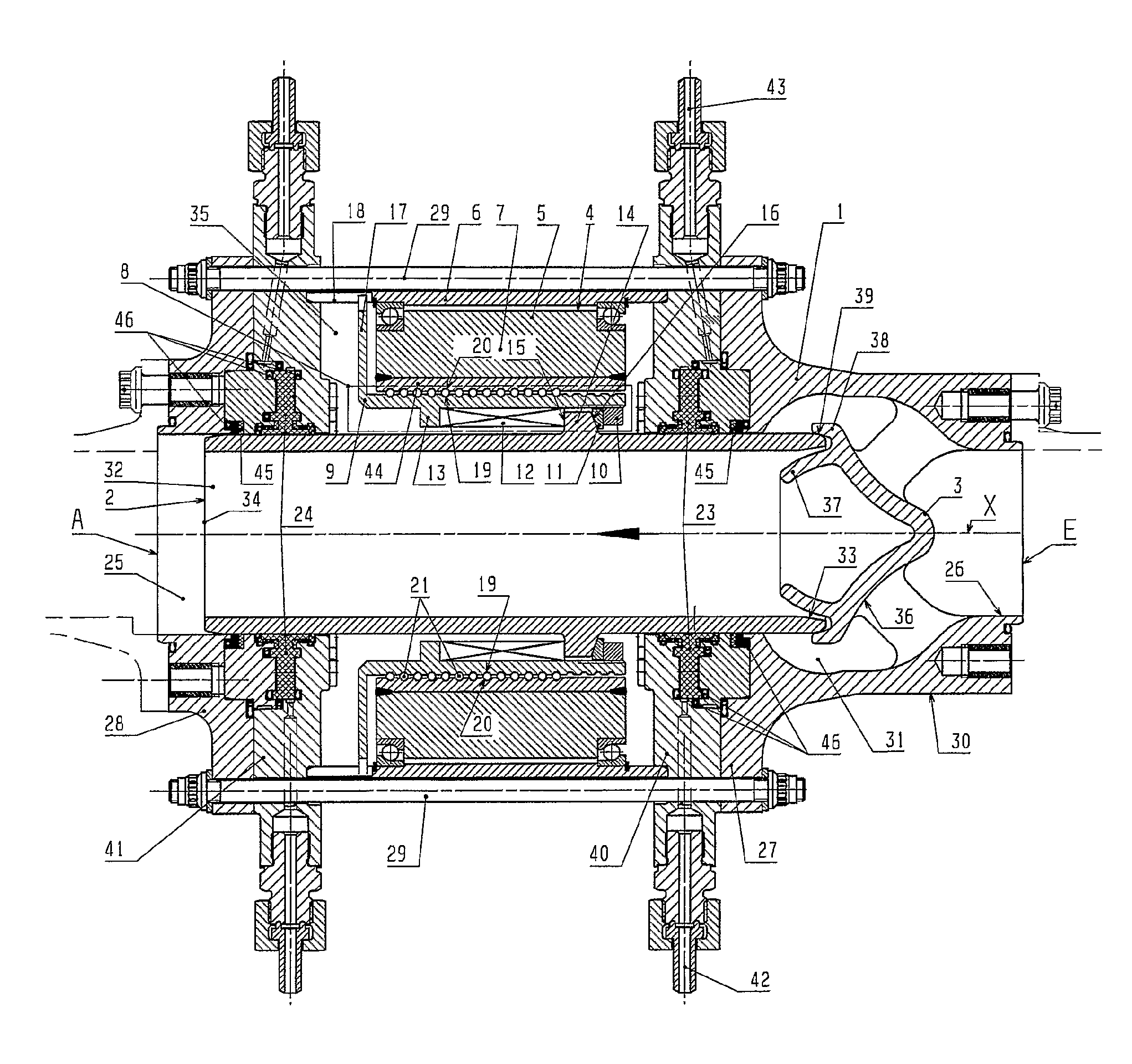
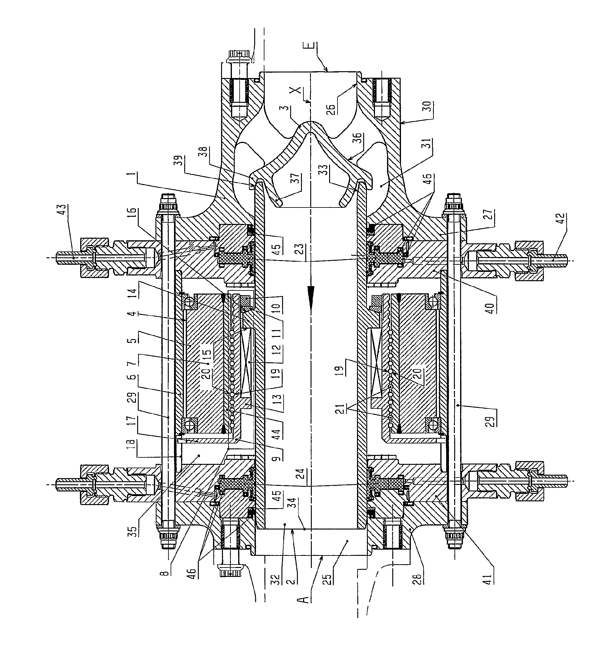
[0030]In a valve housing 1 a flow duct 25 is provided which has a fluid inlet opening E and a fluid outlet opening A. The fluid inlet opening E and the fluid outlet opening A are thus configured at ends of the valve housing 1 remote from one another so that the flow duct 25 extends straight from the fluid inlet opening E to the fluid outlet opening A. The flow duct 25, the fluid inlet opening E and the fluid outlet opening A are configured to be circular in cross section and arranged coaxially relative to one another, comprising a common central axis X.

[0031]The first end-face cover part 27 has a cylindrical housing projection 30 protruding outwardly in the direction of the X-axis, which at its free end is provided with the fluid inlet opening E. In the region of the fluid inlet opening E the flow duct 25 is formed by a first cylindrical bore portion 26. In the interior of the cylindrical housing projection 30 a second bore portion 31 of the flow duct 25 is formed, said bore portion...


PUM


Abstract

A coaxial valve for regulating and blocking a liquid or gaseous medium having a valve housing having at least one inlet opening, at least one outlet opening and a flow duct connecting the at least one inlet opening to the at least one outlet opening; a tubular valve sleeve disposed in an axially movable manner in a portion of the flow duct and having an inflow and an outflow opening for the medium, wherein the inflow and the outflow openings open into the flow duct; a closure member disposed in the valve housing and arranged coaxially with the valve sleeve and configured to close the inflow opening; and a drive configured to axially move the valve sleeve and having an electric servomotor and a transmission part coupled between the servomotor and the valve sleeve, the transmission part configured to transmit an axial movement to the valve sleeve.

Description

[0001]This application is a U.S. National Phase Application under 35 U.S.C. §371 of International Application No. PCT / DE2008 / 001304, filed on Aug. 7, 2008 and claims benefit to German Patent Application No. DE 10 2007 037 995.3, filed on Aug. 10, 2007. The International Application was published on Feb. 19, 2009 as WO 2009 / 021492 under PCT Article 21 (2).[0002]The invention relates to a coaxial valve for regulating and blocking a liquid or gaseous medium, in particular a coaxial valve for cryogenic fluid. The coaxial valve comprises a valve housing, which has at least one inlet opening and one outlet opening and also a flow duct which connects said openings to one another. A tubular valve sleeve is provided, which is provided in an axially movable manner in a portion of the flow duct and which has an inflow opening and an outflow opening for the medium, both of these openings opening out into the flow duct. A closure member provided in the valve housing is arranged coaxially with re...

Claims


Application Information

Patent Timeline
Patent Type & Authority Applications(United States)
IPC IPC(8): F16K31/04
CPCF16K31/047F16K1/123
Inventor GAUSS, ADOLFVOIT, ARNO
Owner ARIANEGRP GMBH
Why Eureka
Try Eureka