

Image sensor and manufacturing method thereof
- Summary
- Abstract
- Description
- Claims
- Application Information
AI Technical Summary
Benefits of technology
Problems solved by technology
Method used
Image


Examples
Embodiment Construction
[0022]Hereinafter, an embodiment of the present invention shall be described in detail with reference to the drawings.
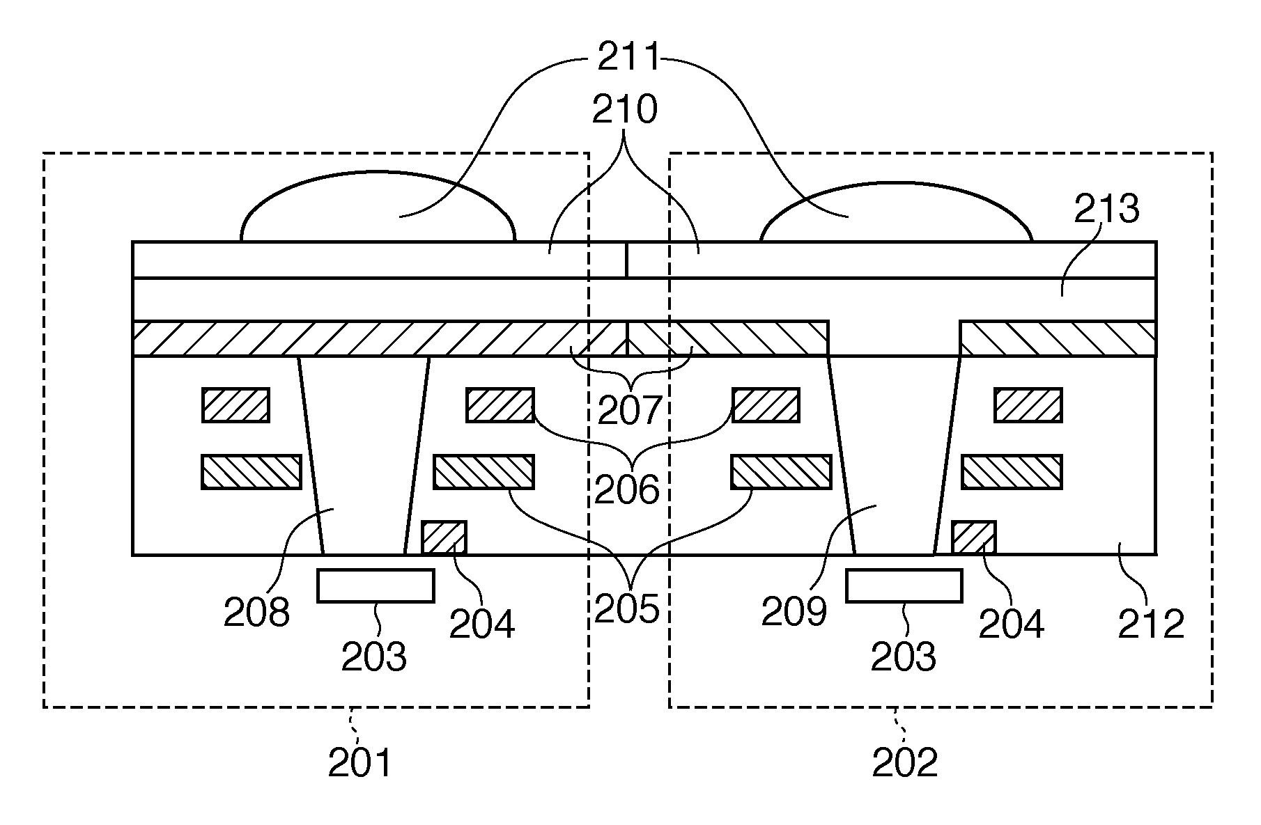
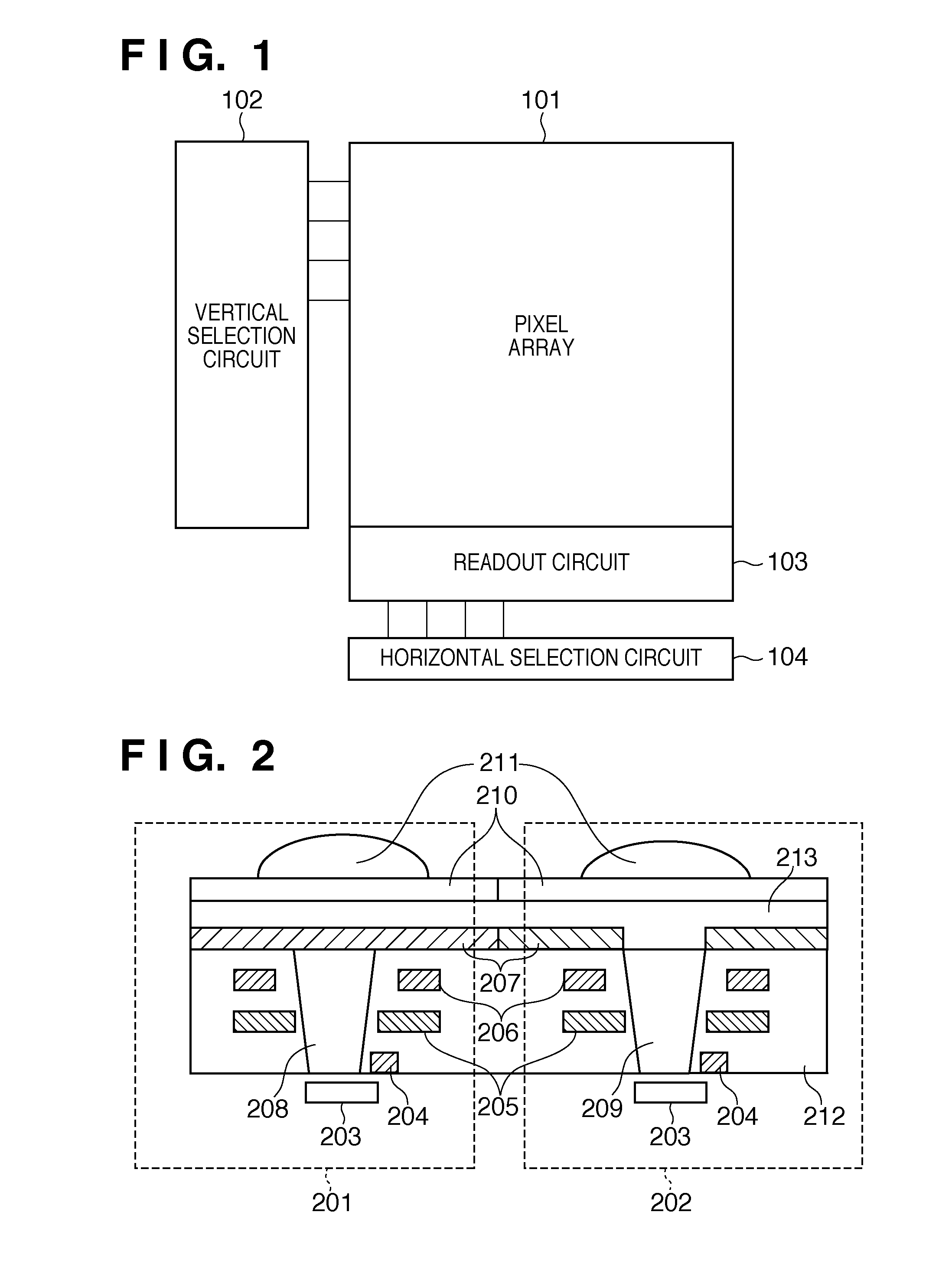
[0023]FIG. 1 is a diagram illustrating the structure of an image sensor according to an embodiment of the present invention.
[0024]The image sensor in FIG. 1 includes a pixel array 101 in which pixels are arrayed two-dimensionally, a vertical selection circuit 102 that selects rows in the pixel array 101, and a horizontal selection circuit 104 that selects columns in the pixel array 101. The image sensor also includes a readout circuit 103 that reads out signals from pixels of the pixel array 101 that have been selected by the vertical selection circuit 102 and the horizontal selection circuit 104. Note that in addition to the constituent elements illustrated in FIG. 1, the image sensor also includes, for example, a timing generator that manages the timing of the vertical selection circuit 102, the horizontal selection circuit 104, and the readout circuit 103, a contr...
PUM
 Abstract
Description
Claims
Application Information