Keel-free direct hanging fastener

A technology for hanging fasteners and backbones, which is applied in the field of parts or components, and can solve the problems of large contact area between fasteners and thermal insulation boards, thermal insulation decorative panels without keels, etc.

Inactive Publication Date: 2009-01-07
张俊尧
View PDF0 Cites 6 Cited by
  • Summary
  • Abstract
  • Description
  • Claims
  • Application Information

AI Technical Summary

Problems solved by technology

[0003] The object of the present invention is to provide a keel-free hanging fastener, which solves the problem of no keel hanging on the thermal insulation decorative board. It includes anchors and fasteners. The anchors are expansion bolts. Inner wire round hole, the fastener is connected with the expansion bolt by screw. The fastener is composed of a top plate and a bottom plate. There is a round hole in the center of the top plate and bottom plate of the fastener. The hole diameter of the top plate corresponds to the diameter of the screw, and the bottom plate has a round hole The hole diameter corresponds to the diameter of the expansion bolt screw. The top plate of the fastener is a flat plate or two positive and negative "L" shaped plates are arranged perpendicular to the surface of the top plate and the long side on both sides of the round hole. The bottom plate of the fastener is a flat plate or both ends Folded in half to form a "U" shape, the material used for the fasteners

Method used


Image

  • Keel-free direct hanging fastener
  • Keel-free direct hanging fastener
  • Keel-free direct hanging fastener

Examples


Embodiment Construction

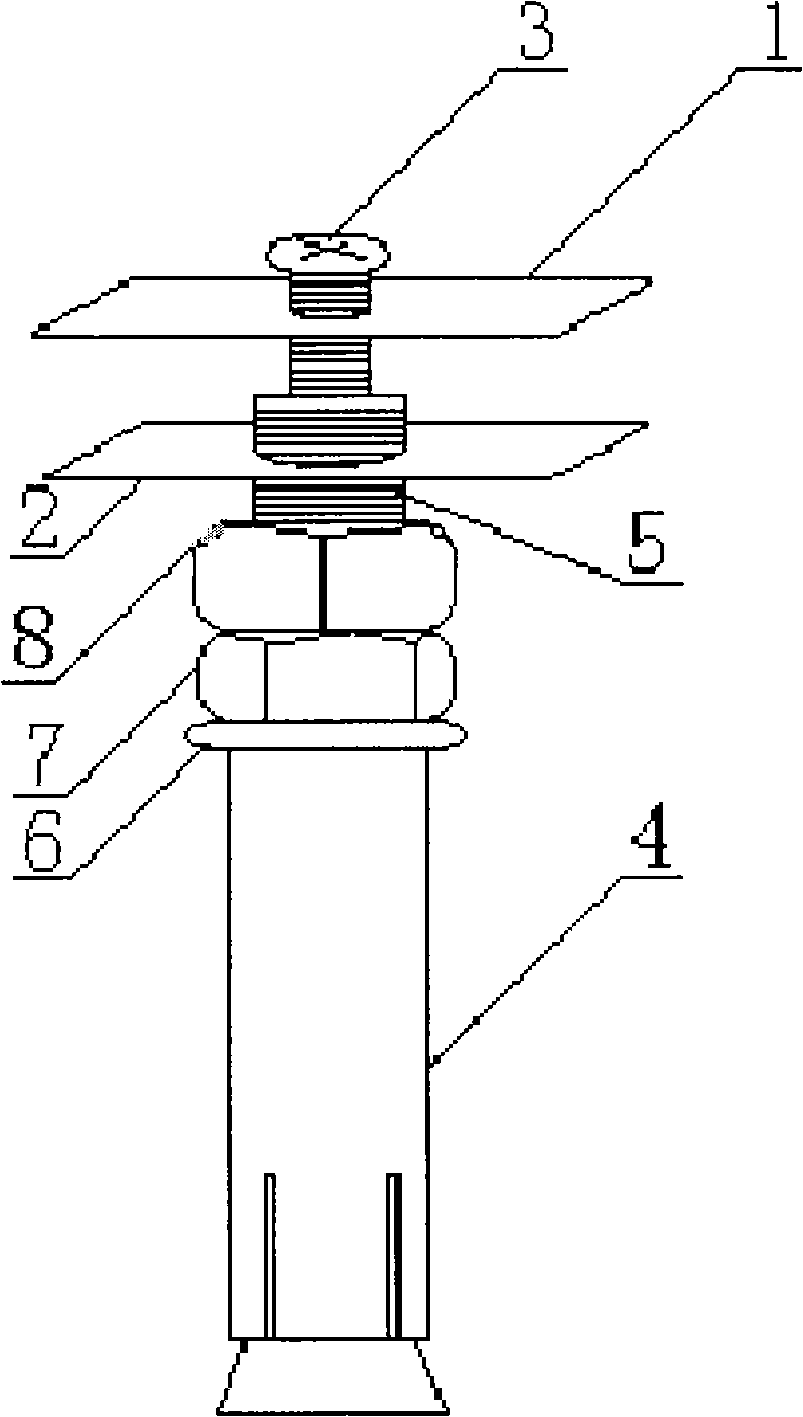
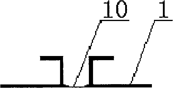
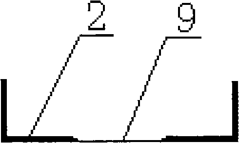
[0007] Combine below figure 1 , figure 2 and image 3 The keelless backbone hanging fastener of the present invention is further described. It includes an anchor and a fastener. It is connected with the screw rod 5 of the expansion bolt 4. The fastener is composed of a top plate 1 and a bottom plate 2. A round hole is opened in the center of the top plate 1 and bottom plate 2 of the fastener. The diameter of the hole 10 on the top plate corresponds to the diameter of the screw 3. The hole diameter corresponds to the diameter of the screw 5 of the expansion bolt 4. The top plate 1 of the fastener is a flat plate or two positive and negative "L" shaped plates are arranged perpendicular to the surface of the top plate 1 and the long side on both sides of the round hole, and the bottom plate of the fastener 2 It is a flat plate or both ends are folded inward to form a "U" shape, and the material used is stainless steel or metal with surface anti-corrosion treatment. Constructi...


PUM


Abstract

The invention relates to a non-keel dry-hanging fastener which belongs to the technical field of parts or structures especially used as fixing material during decorating walls of buildings. The non-keel dry-hanging fastener solves the problem that thermal-insulation decoration plates have no keel dry-hangings and comprises a clip and a fastening piece, wherein, the clip is an expansion bolt, and the center of the threaded rod of the expansion bolt is provided with an inner-threaded round hole; the fastening piece is connected with the threaded rod of the expansion bolt by a screw. The fastening piece consists of a top plate and a base plate which are respectively provided with a round hole. The fastener provided by the invention is made of stainless steel or metal, the surface of which is treated to resist against corrosion, and realizes that thermal-insulation decoration plates have no keel dry-hangings, so that thermal-insulation decoration plates can be perfectly fixed on walls. The fastener is applicable to various wall materials, such as concrete, solid and hollow walls and can make constructions and maintenance convenient and quick. The fastener has high loading capacity, high bearing pressure and good tension-resistance performance; besides, the fastener can prevent the impact damage, reduce the loading of a whole building, provide 3-5 cm horizontal adjustment differences for the distorted surfaces of walls, and provide flat surfaces for wall decoration.

Description

1. Technical field [0001] The invention belongs to the technical field of parts or components specially used as fixing materials for building wall decoration, and in particular relates to an anchor bolt for fixing an exterior thermal insulation decorative board. 2. Background technology [0002] Practices at home and abroad have shown that the use of external thermal insulation technology and products for buildings is the most scientific, reasonable and economical means of building energy conservation. The so-called external thermal insulation refers to the construction of thermal insulation layers on the outer surface of the vertical external wall. my country's building energy conservation work started relatively late, and the thermal insulation and energy saving renovation of existing buildings is no less difficult than new construction projects, and its construction difficulty is far greater than that of new buildings; moreover, the wall structures and finishes of existing...

Claims


Application Information

Patent Timeline
IPC IPC(8): E04F13/22
Inventor 张俊尧
Owner 张俊尧
Why Eureka
Try Eureka