
Semiconductor device including dummy gate part and method of fabricating the same

a technology of semiconductor substrate and gate part, which is applied in the direction of semiconductor substrate, electrical apparatus, basic electric elements, etc., can solve the problems of defective pattern and defect pattern in the formation of circuit pattern, and achieve the effect of reducing density difference, facilitating shallow trench isolation operation, and reducing the level difference between certain material layers on semiconductor substra

Active Publication Date: 2012-02-02
SAMSUNG ELECTRONICS CO LTD
View PDF9 Cites 7 Cited by
  • Summary
  • Abstract
  • Description
  • Claims
  • Application Information

AI Technical Summary

Benefits of technology

[0014]The present invention provides a semiconductor device, in which a difference in height between upper surfaces of a cell region and a peripheral region (herein referred to as level difference) can be decreased by forming dummy gate parts in the peripheral region, and a method of fabricating the semiconductor device, to resolve problems which occur in the prior art.
[0015]The present invention also provides a reliable semiconductor device, in which the level difference between a cell region and a peripheral region is minimized by optimizing dummy gate parts, and a method of fabricating the semiconductor device.
[0027]The overall surface area of the dummy gate parts may be controlled to decrease density difference between the real gate parts in the cell region and the dummy gate parts in the peripheral region.
[0028]According to the present invention, the density of dummy gate parts can be controlled freely as occasion demands when the density of dummy active region is optimized, and thus the level difference between certain material layers on a semiconductor substrate can be decreased.
[0029]According to the present invention, the density of dummy active regions can be maintained within proper range without concerning the controlling density of dummy gate parts, and thus a shallow trench isolation (STI) operation can be performed smoothly.

Problems solved by technology

The high density of circuit patterns causes various problems during manufacturing of semiconductor devices, and thus new methods of manufacturing semiconductor devices are being developed.
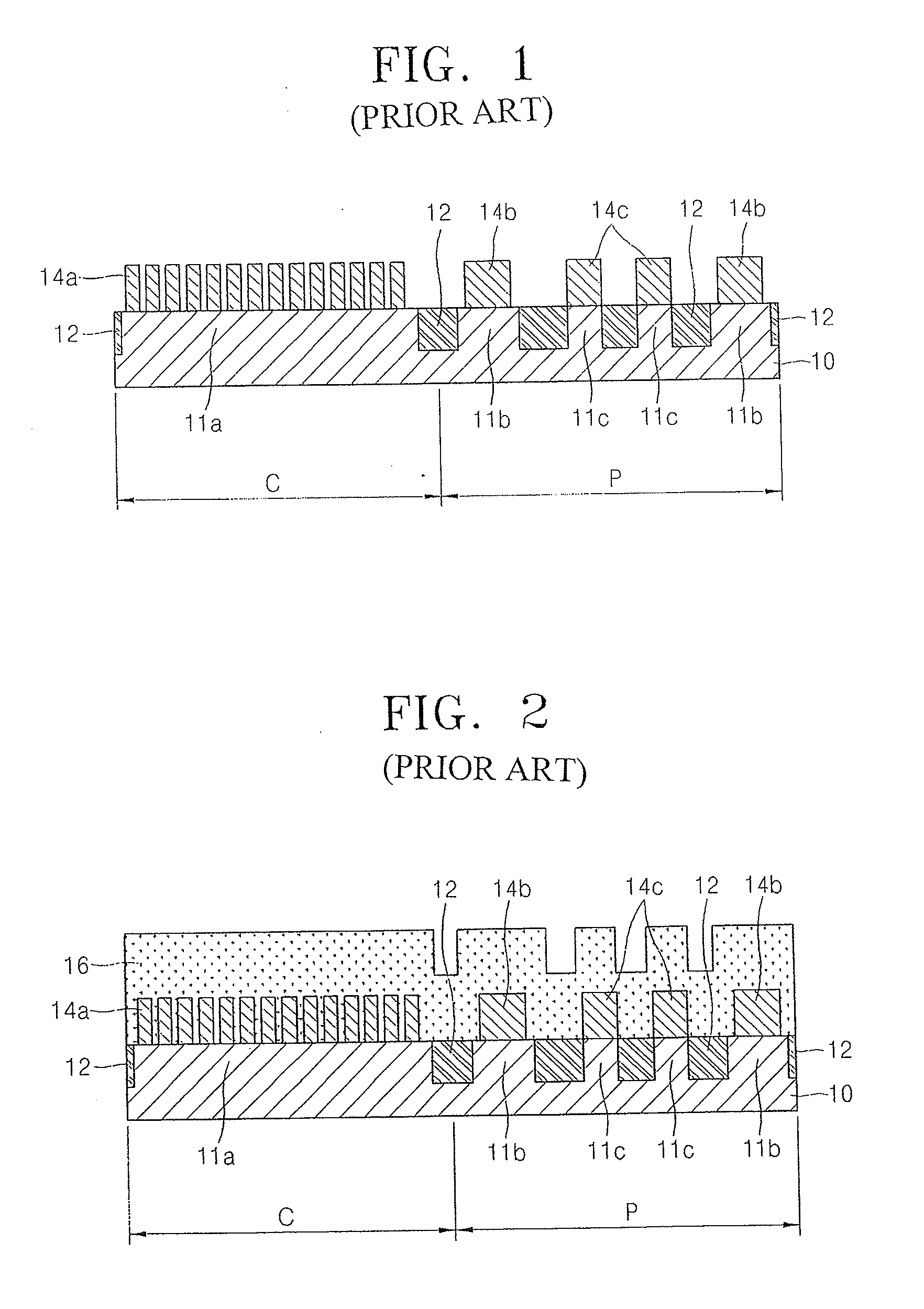
However, due to the formation of gate patterns in a cell region, the interlayer insulation layer will not be level with a peripheral region even after CMP.
If a pattern corresponding to the circuit pattern is formed on the interlayer insulation layer, it may cause a defective pattern due to the lack of a defocus margin.
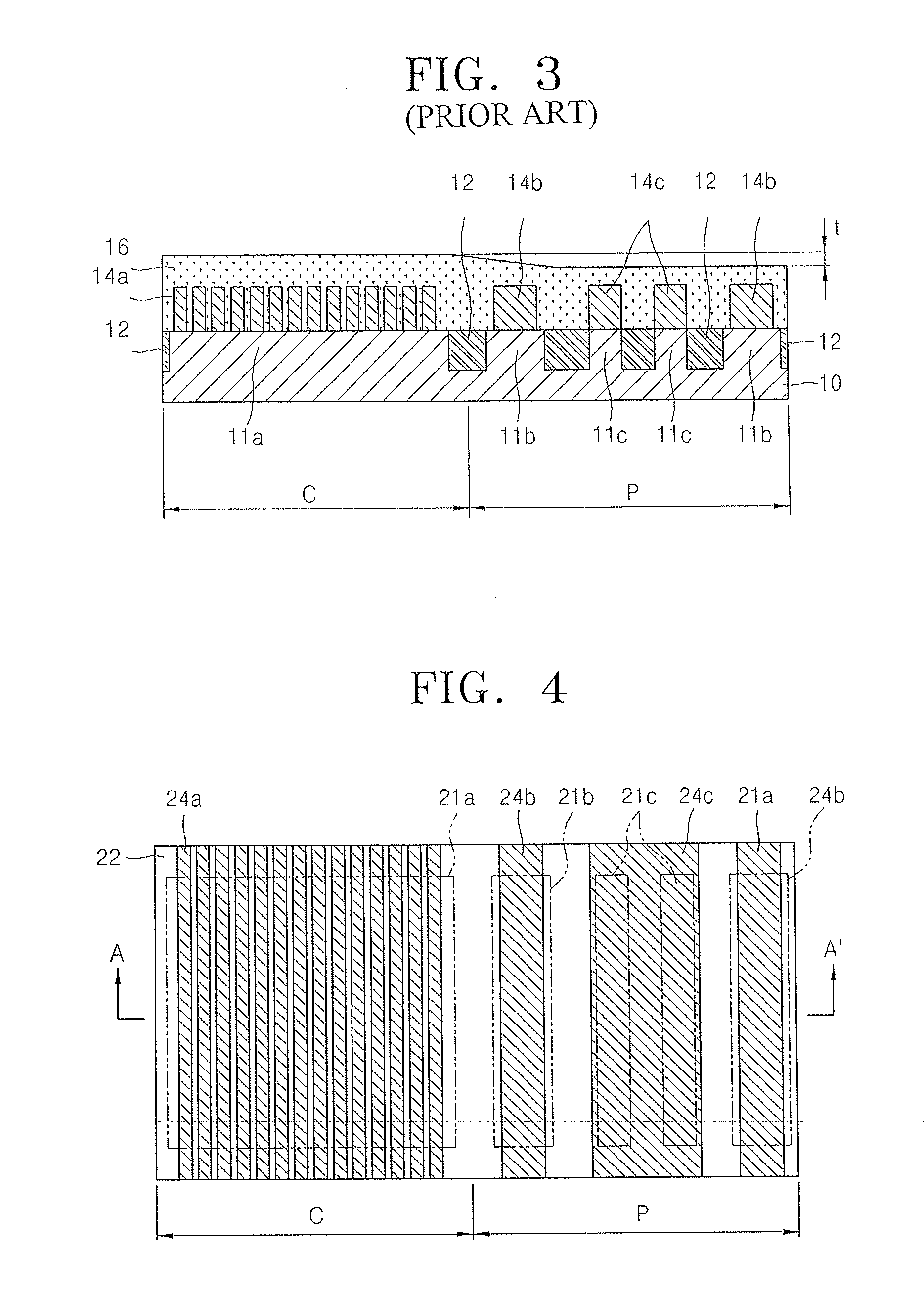
Therefore, a circuit layer or another interlayer insulation layer (not shown), which is to be formed on the interlayer insulation layer, cannot be formed evenly due to the level difference t between the cell region C and the peripheral region P, and thus the unevenness may cause a defective pattern in the formation of circuit patterns.

Method used


Image

  • Semiconductor device including dummy gate part and method of fabricating the same
  • Semiconductor device including dummy gate part and method of fabricating the same
  • Semiconductor device including dummy gate part and method of fabricating the same

Examples


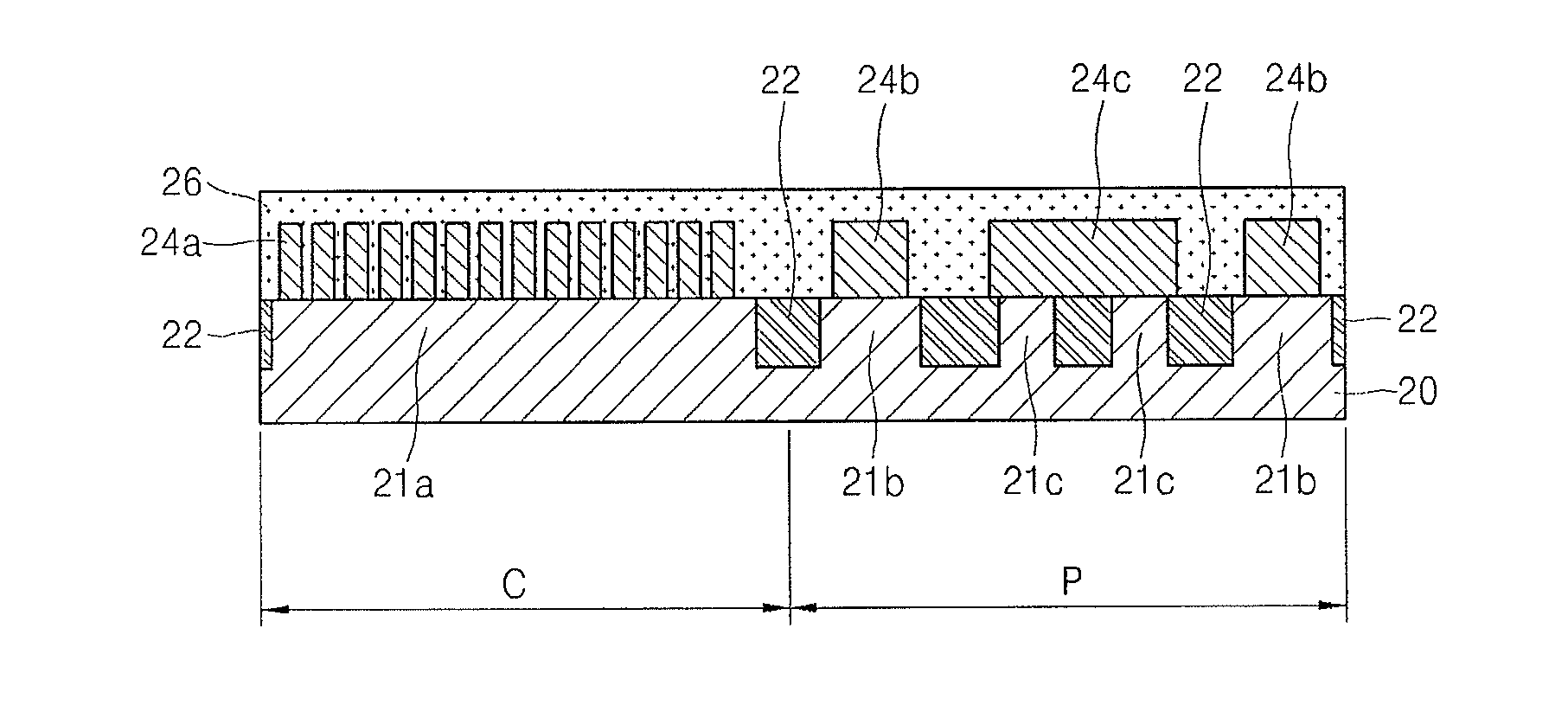
Embodiment Construction

[0036]FIG. 4 is a plan view of a semiconductor device according to an embodiment of the present invention, and FIGS. 5 through 7 are sectional views illustrating a process FOR manufacturing the semiconductor device, taken along line A-A′ of FIG. 4.

[0037]Referring to FIGS. 4 and 5, the top surface of a semiconductor substrate 20, which is, for example, formed of a silicon single crystal, is divided into two regions: a cell region C, on which semiconductor memory devices will be formed, and a peripheral region P, which is formed around the cell region C and on which some control devices and dummy devices will be formed. A real active region 21a, surrounded and defined by a device isolating region 22, is formed in the cell region C. A plurality of dummy active regions 21c, surrounded and defined by the device isolating region 22, are formed in the peripheral region P. Real active regions 21b are also formed in the peripheral region P. When the peripheral region P is formed as a single ...


PUM

PropertyMeasurementUnit
densityaaaaaaaaaa
impurityaaaaaaaaaa
clarityaaaaaaaaaa

Abstract

In a reliable semiconductor device and a method of fabricating the semiconductor device, a difference in height between upper surfaces of a cell region and a peripheral region (also referred to as a level difference) is minimized by optimizing dummy gate parts. The semiconductor device includes a semiconductor substrate including a cell region and a peripheral region surrounding the cell region, a plurality of dummy active regions surrounded by a device isolating region and formed apart from each other, and a plurality of dummy gate parts formed on the dummy active regions and on the device isolating regions located between the dummy active regions, wherein each of the dummy gate parts covers two or more of the dummy active regions.

Description

CROSS-REFERENCE TO RELATED PATENT APPLICATION[0001]This application is a divisional application of U.S. patent application Ser. No. 12 / 291,211 filed on Nov. 7, 2008, which claims the benefit of Korean Patent Application No. 10-2007-0113719, filed on Nov. 8, 2007, in the Korean Intellectual Property Office, the contents of which are incorporated herein in their entirety by reference.BACKGROUND OF THE INVENTION[0002]1. Field of the Invention[0003]The present invention relates to a semiconductor device, and more particularly, to a semiconductor device, in which a dummy gate part is formed in a peripheral region, and a method of fabricating the same.[0004]2. Description of the Related Art[0005]As semiconductor devices continue to be more densely integrated, individual circuit patterns are becoming more densely arranged to attempt to include more semiconductor devices within the same area. The high density of circuit patterns causes various problems during manufacturing of semiconductor ...

Claims


Application Information

Patent Timeline
Patent Type & Authority Applications(United States)
IPC IPC(8): H01L21/76
CPCH01L21/31053H01L27/1052H01L29/66545H01L27/105H10B99/00H01L21/823437
Inventor KWON, BYOUNG-HOJO, SANG-YOUNCHOI, JIN-SOOKHONG, CHANG-KIYOON, BO-UNKIM, HONG-SOOYUN, SE-RAH
Owner SAMSUNG ELECTRONICS CO LTD
Learn More