Image display device and image display device drive method

Inactive Publication Date: 2012-01-19
SHARP KK
View PDF10 Cites 62 Cited by
  • Summary
  • Abstract
  • Description
  • Claims
  • Application Information

AI Technical Summary

Benefits of technology

[0010]However, the technique disclosed in Patent Literature 1 etc. is developed mainly for reducing electric power consumption, or for alleviating eye fatigue. Thus, televisi

Problems solved by technology

Such a television receiver has another problem that a viewer would feel a sense of discomfort as to the

Method used


Image

  • Image display device and image display device drive method
  • Image display device and image display device drive method
  • Image display device and image display device drive method

Examples


Example

[0029]In the following, one embodiment of the present invention is described referring to FIGS. 1 to 5.

[0030](Example of Configuration of Image Display Device)

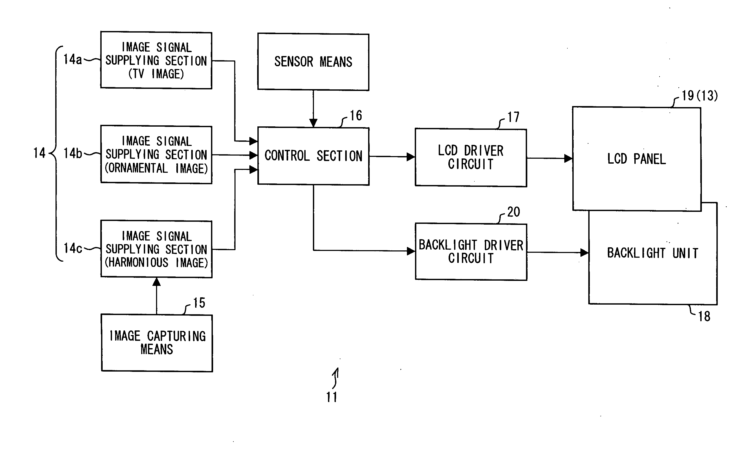
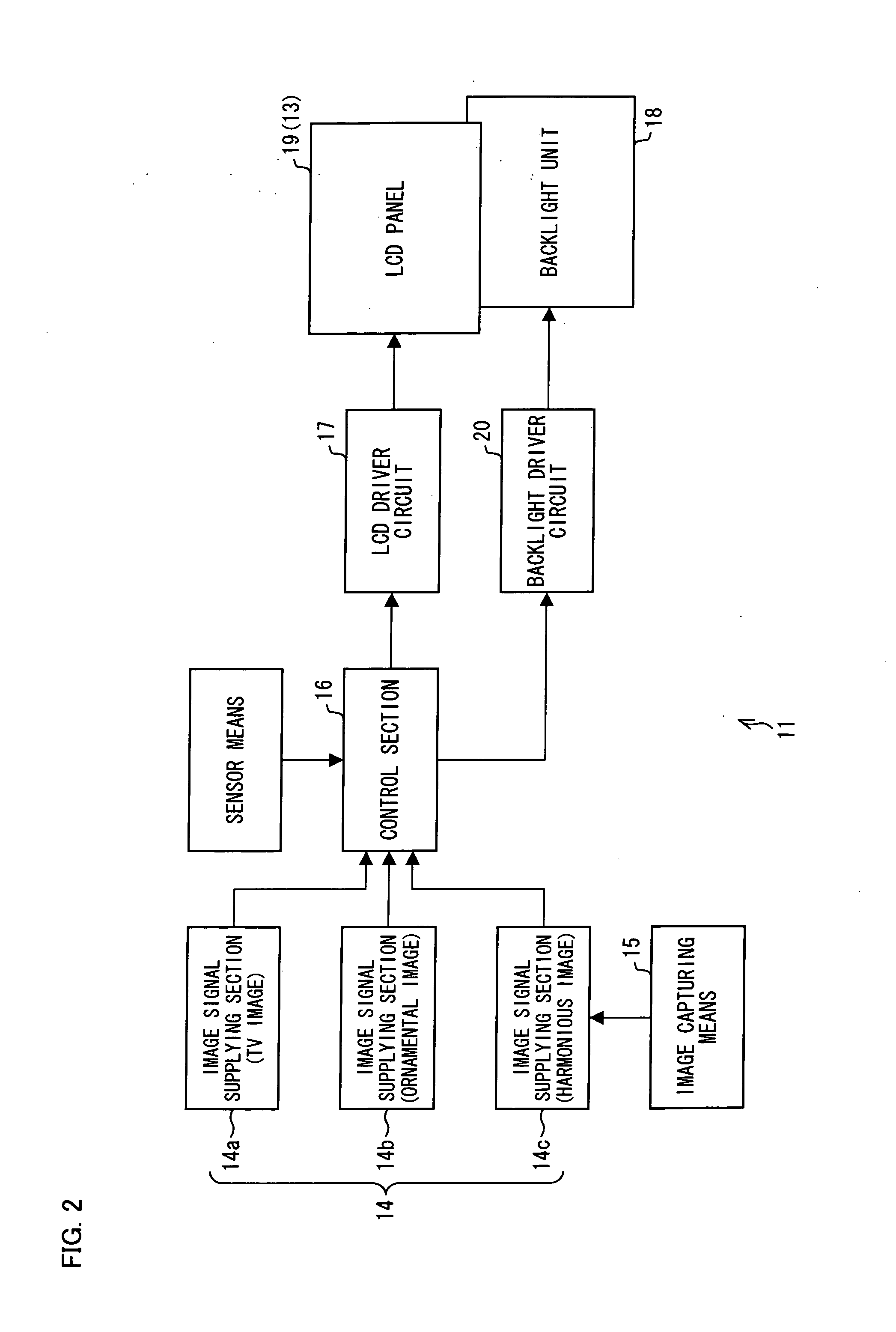
[0031]FIG. 2 is a schematic block diagram illustrating a configuration of a television receiver (image display device) 11 as one example of an image display device according to the present invention. As illustrated in FIG. 2, the television receiver 11 includes an LCD (Liquid Crystal Display) panel (display section) 19, a backlight unit 18, an LCD driving circuit 17, a backlight driver circuit 20, a control section 16, an image capturing means 15, an image signal supplying section 14, and a tuner (not illustrated). Here, the LCD driver circuit 17 includes a signal line driver circuit and a scanning line driver circuit.

[0032]The image signal supplying section 14 includes an image signal supplying sections 14a, 14b, and 14c. The image signal supplying section 14a is configured to supply to the control section 16 an image signal ...


PUM


Abstract

A television receiver according to at least one embodiment of the present invention includes a display section capable of displaying a TV image and a harmonious image being in harmony with a wall surface against which the image display device is provided.

Description

TECHNICAL FIELD[0001]The present invention relates to an image display device having a display mode in which an image in conformity with an environment in which the image display device is installed is displayed, and a drive method for driving such an image display device.BACKGROUND ART[0002]For home electronics, it has been a demand for products whose presence is not so uncomfortable when the products are not in use for their primary functions. Among such home electronics, image display devices such as television receivers have been getting larger in size, whereby their presence is getting more uncomfortable. Therefore, the aforementioned demand is getting higher for image display devices.[0003]Their display section occupies a majority of an outer appearance of these image display devices, thereby being eye-catching. Thus, it is desirable to improve the display section in this regard. In the following, this problem is explained in more details, referring to a television receiver (i...

Claims


Application Information

Patent Timeline
IPC IPC(8): G09G5/10G09G5/00H04N5/44H04N7/16
CPCG09G5/00G09G2340/12H04N21/4436H04N7/163H04N21/4223H04N5/44
Inventor ICHIOKA, HIDEKIKUSUMOTO, TOSHIHARU
Owner SHARP KK
Why Eureka
Try Eureka