Apparatus and method to prevent bottle rotation

a bottle and apparatus technology, applied in the direction of caps, rotating screw stopper insertion, application, etc., can solve the problems of line interruption, bottle or container base damage, etc., to reduce or eliminate the damage to the base, and reduce or eliminate the effect of compressive for

Inactive Publication Date: 2012-01-26
BEVCORP
View PDF3 Cites 24 Cited by
  • Summary
  • Abstract
  • Description
  • Claims
  • Application Information

AI Technical Summary

Benefits of technology

[0020]The present invention provides an improved device or method for preventing rotation of a bottle or container of the type having a body with a flange below a neck on the top of the bottle or container. The invention is particularly applicable for use with a plastic bottle or container having a generally cylindrical body with a flange below a threaded neck on the top of the bottle or container. Although the invention is particularly directed to plastic bottles or containers, other types of bottles or containers can be used such as, but not limited to, metal bottles, and the like. The body of the bottle or container can have a shape other than a generally cylindrical shape. The bottle or container that can be used in the improved device or method can have a variety of shapes such as, but not limited to, a flat base, a pedaloid base, a champagne-type base, and the like. The invention is particularly applicable to the beverage industry, and more applicable to the non-carbonated beverage industry; however, the invention is equally applicable to the carbonated beverage industry. In addition, the present invention is applicable to the bottling of liquids in bottles or containers other than beverages (e.g., cleaning products, automotive products, paint products, etc.). In accordance with the present invention, there is provided a bottle support plate that at least partially supports the bottle or container at the flange below the neck of the bottle or container during the capping process. The support plate is designed to at least partially counter the axially downward force exerted on the bottle or container when the capping machine exerts a downward force on the top of the bottle or container as the cap is being applied to the bottle or container. The counter-active effect of the support plate results in a reduction or elimination of compressive force exerted on the body and / or base of the bottle or container. As a result, damage to the base and / or body of the bottle or container is reduced or eliminated during the capping process. The support plate can also or alternatively be designed to at least partially counter the axially downward force exerted on the bottle or container when the bottle or container is filled with a fluid. Depending on the flow rate of fluid into the bottle or container, the viscosity of the fluid, and / or the temperature of the fluid, the fluid can cause damage to the base of the bottle or container during the filling process. The support plate can reduce or eliminate such damage to the base of the bottle or container during the filling process by partially or fully supporting the bottle or container such the base of the bottle of the container does not bear the full load or force of the fluid during the filling process. The support plate can be made from a number of different materials that are resistant to wear and which can support the weight of the bottle or container during the capping and / or filling process. Such materials include, but are not limited to metal (e.g., stainless steel, aluminum, etc.), plastics, fiberglass, rubber, etc.

Problems solved by technology

Depending on the flow rate of fluid into the bottle or container, the viscosity of the fluid, and / or the temperature of the fluid, the fluid can cause damage to the base of the bottle or container during the filling process.
Although the size variation in the region below the bottle flange is generally small, such variation can cause line interruptions resulting from the bottle not being properly positioned during the capping process.

Method used


Image

  • Apparatus and method to prevent bottle rotation
  • Apparatus and method to prevent bottle rotation
  • Apparatus and method to prevent bottle rotation

Examples


Embodiment Construction

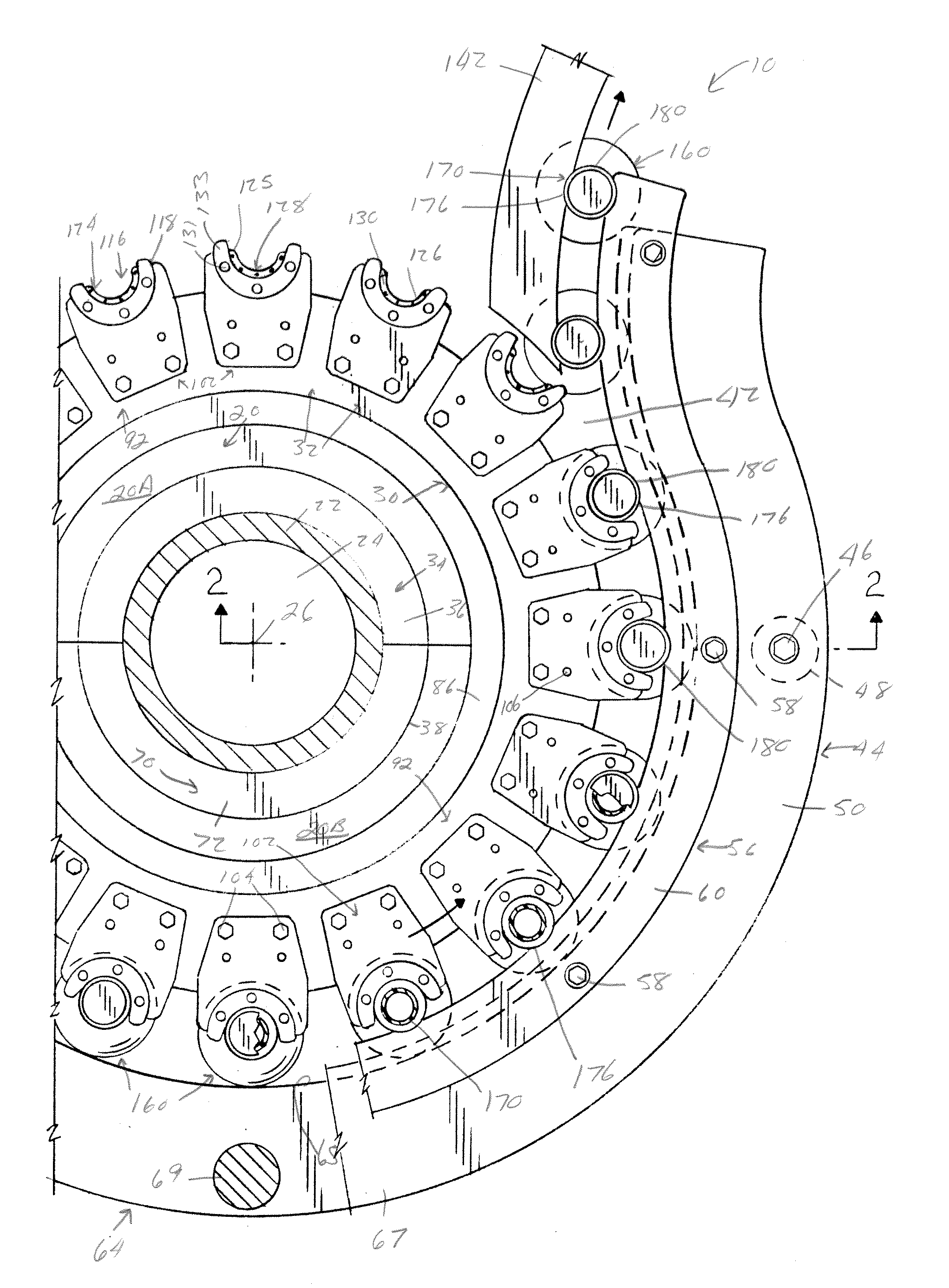
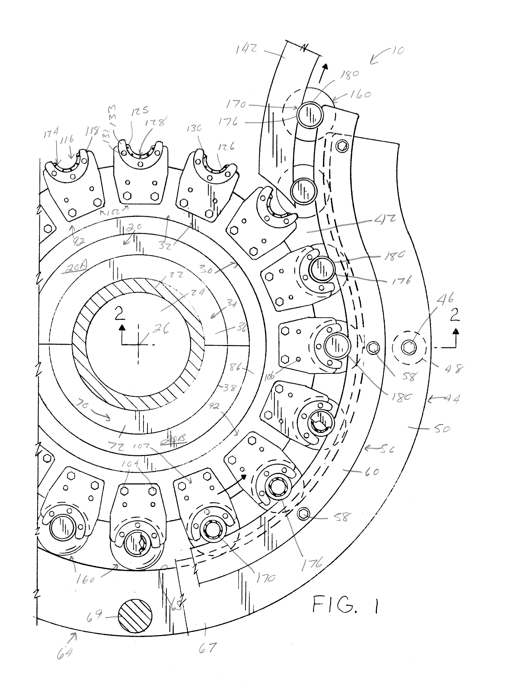
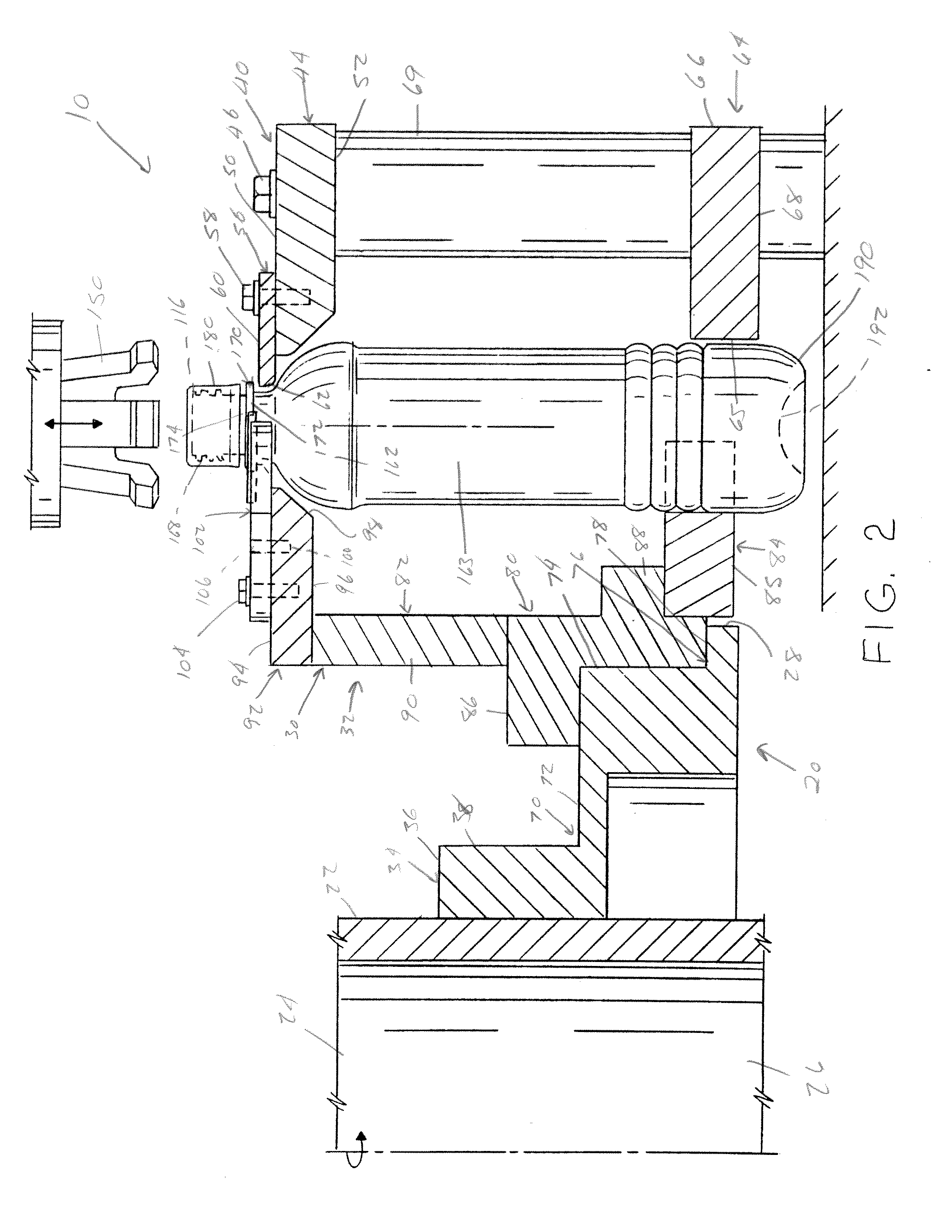
[0049]Referring now to the drawings wherein the showing is for the purpose of illustrating preferred embodiments of the invention only and not for the purpose of limiting the same, FIGS. 1-3 illustrate various portions of what is defined as a bottling machine 10. The bottling machine as defined herein includes the tilling and / or the capping bottling equipment. The filling equipment is that which tills containers with product, such as, but not limited to, a non-carbonated beverage. The capping equipment is that which applies a cap, crown or other closure to the container.

[0050]Bottling machine 10 includes a rotatable star wheel 20 and a rear container guide assembly 40 spaced radially outwardly from rotatable star wheel 20 for retaining the bottles 160 within rotatable star wheel 20. Depending upon the application of bottling machine 10, an additional star wheel (not shown) or conveyor (not shown) is mated to rotatable star wheel 20 at a fixed entry point (not shown) on rotatable sta...


PUM


Abstract

A bottle support plate for use in a rotary capping machine to apply caps onto the upper threaded neck of one or more containers having a circular flange as the containers are moved along a generally circular path by a star wheel. The bottle support plate includes a pocket that at least partially supports and at least partially mates with the flange of the container to at least partially inhibit rotation of the container during the threading of a cap on an upper threaded neck of the container. The pocket includes a support ledge having an upper surface, a neck cavity, a ledge wall extending upwardly from the upper surface of said support ledge and a non-smooth surface on upper surface of the support ledge. The ledge wall is designed to be at least partially mateable with at least a portion of an outer peripheral edge of the flange of the container. The neck cavity is designed to receive a portion of a neck of the container that is located below the container flange. The non-smooth surface is designed to engage a portion of the bottom surface of the bottle flange and inhibit or prevent rotation of the bottle when a cap is twisted onto the upper threaded neck of the container.

Description

[0001]The present invention claims priority on U.S. Provisional Application Ser. No. 61 / 366,254 filed Jul. 21, 2010, which is incorporated herein by reference.[0002]The present invention relates to the art of capping plastic bottles or containers as they are moved along a preselected path, and more particularly to an improvement in a capping machine which prevents rotation of the plastic bottle or container while a cap is being tightened onto the neck of the bottle. The invention is particularly applicable to a container guide which retains the bottles or containers in the tilling or capping machine as the bottles or containers pass through the machine and will be described with particular reference thereto.BACKGROUND OF THE INVENTION[0003]Blow-molded plastic bottles for containing liquids are known and have found increasing acceptance. Such containers are accepted particularly in the beverage industry as disposable containers for use with effervescent or carbonated beverages and no...

Claims


Application Information

Patent Timeline
Patent Type & Authority Applications(United States)
IPC IPC(8): B67B3/20
CPCB67B3/206
Inventor PERONEK, MICHAEL H.
Owner BEVCORP
Why Eureka
Try Eureka