Systems and Methods for Liquid Level Sensing Having a Differentiating Output

Active Publication Date: 2012-01-26
ROSEMOUNT AEROSPACE
View PDF5 Cites 6 Cited by
  • Summary
  • Abstract
  • Description
  • Claims
  • Application Information

AI Technical Summary

Problems solved by technology

An early shutdown could prevent the launch vehicle from reaching orbit; a late shutdown could result in an engine failure.
Conventional liquid level sensing systems for launch vehicle applications use a bare wire sensing element that adequately meets system response requirements (<160 ms), but is very fragile.
However, the fragility of the conventional sensing element is problematic, especially for newer launch vehicles that experience significantly higher pyrotechnic shock levels.
In addition, at cryogenic temperatures, the low resistance (˜1 ohm) of the conventional liquid level sensors interferes with circuit fault detection.

Method used


Image

  • Systems and Methods for Liquid Level Sensing Having a Differentiating Output
  • Systems and Methods for Liquid Level Sensing Having a Differentiating Output
  • Systems and Methods for Liquid Level Sensing Having a Differentiating Output

Examples


Embodiment Construction

[0026]This disclosure describes a liquid level sensing system that uses a plurality of discrete-point level sensing elements to rapidly detect the transition from liquid to gas or from gas to liquid within a tank or other enclosure by using a differentiating technique.

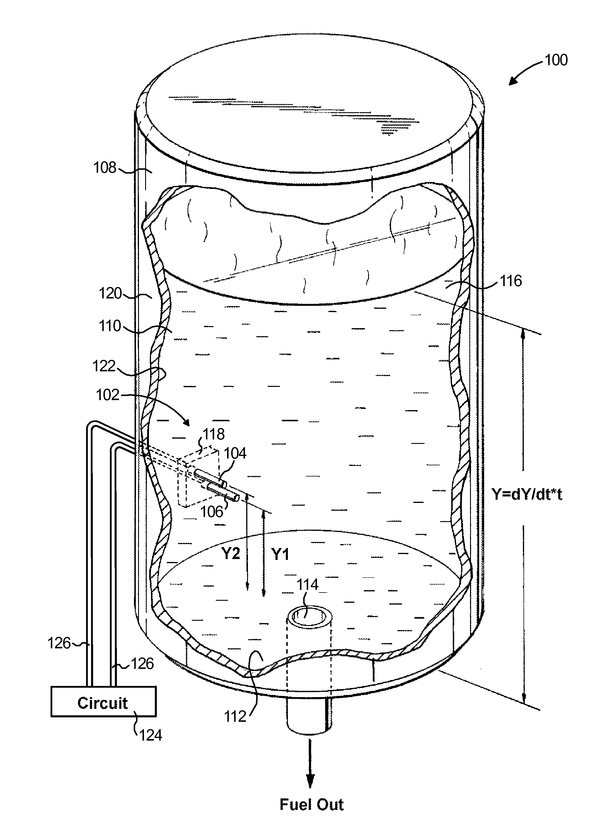
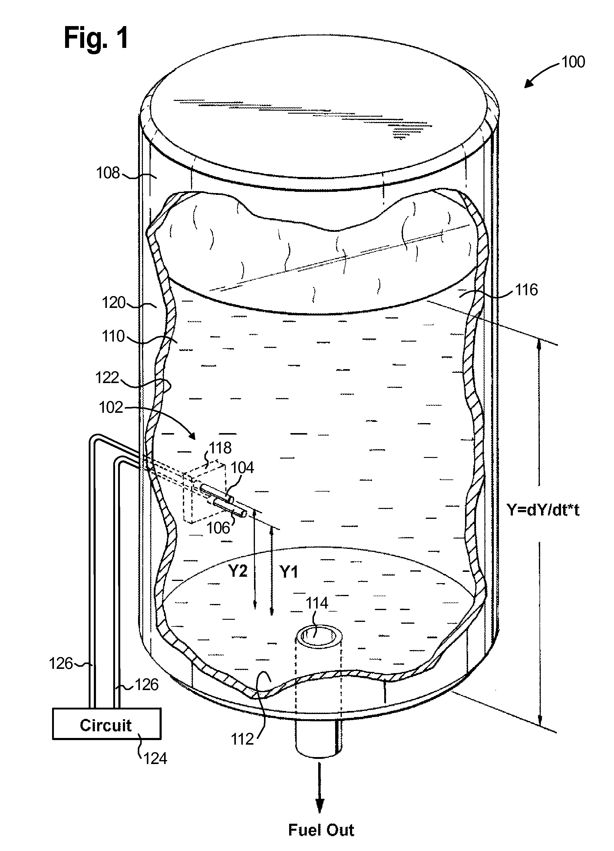
[0027]Reference will now be made in detail to the present preferred embodiments of the liquid level sensing system, examples of which are shown in the drawings. For purposes of explanation and illustration, and not limitation, a perspective view of a first exemplary embodiment of the liquid level sensing system of the present invention is shown in FIG. 1 and is designated generally by reference numeral 100.

[0028]System 100 includes a sensing unit 102 having a first sensing probe 104 and a second sensing probe 106. Sensing unit 102 is mounted within a liquid holding tank 108 having at least one side wall 110 and a floor 112, with an outlet orifice 114 formed within floor 112 to allow a liquid 116 to exit the tank 108. A...


PUM


Abstract

A liquid level sensing system including a housing configured to hold a liquid, a first temperature sensor connected to the housing and configured to output a first signal representing a first temperature measured at the first temperature sensor, a second temperature sensor connected to the housing and configured to output a second signal representing a second temperature measured at the second temperature sensor, and a circuit configured to receive the first and second signals as input and to provide an output signal proportional to the time rate of change of the difference between the first signal and the second signal.

Description

BACKGROUND OF THE INVENTION[0001]1. Field of the Invention[0002]The present invention relates to discrete point liquid level sensing within an enclosure, and more particularly to a rapid-response liquid level sensing system that includes two temperature sensing probes and a circuit that produces an output proportional to the time rate of change of the difference between the two signals received from the temperature sensing probes.[0003]2. Description of Related Art[0004]For aerospace launch vehicle applications using liquid propellant, precisely determining when a fuel tank has been depleted during flight is critically important to ensure proper engine cutoff. Typically, several sensors within a fuel tank of the launch vehicle monitor the liquid level in the fuel tank as the fuel exits the tank. The sensors function to prevent the engines of the launch vehicle from shutting down either too early or too late. An early shutdown could prevent the launch vehicle from reaching orbit; a l...

Claims


Application Information

Patent Timeline
IPC IPC(8): G01F23/00
CPCG01F23/242G01F23/248G01F23/247G01F23/243
Inventor PHILLIPS, RICHARD W.EM, CHANSAY
Owner ROSEMOUNT AEROSPACE
Why Eureka
Try Eureka