

Electronic clinical thermometer
a technology of electronic thermometers and clinical thermometers, applied in the field of electronic thermometers, can solve the problems that the method cannot fully take into account individual variations of patients or environmental changes, and achieve the effect of convenient taking
- Summary
- Abstract
- Description
- Claims
- Application Information
AI Technical Summary
Benefits of technology
Problems solved by technology
Method used
Image

Examples
first embodiment
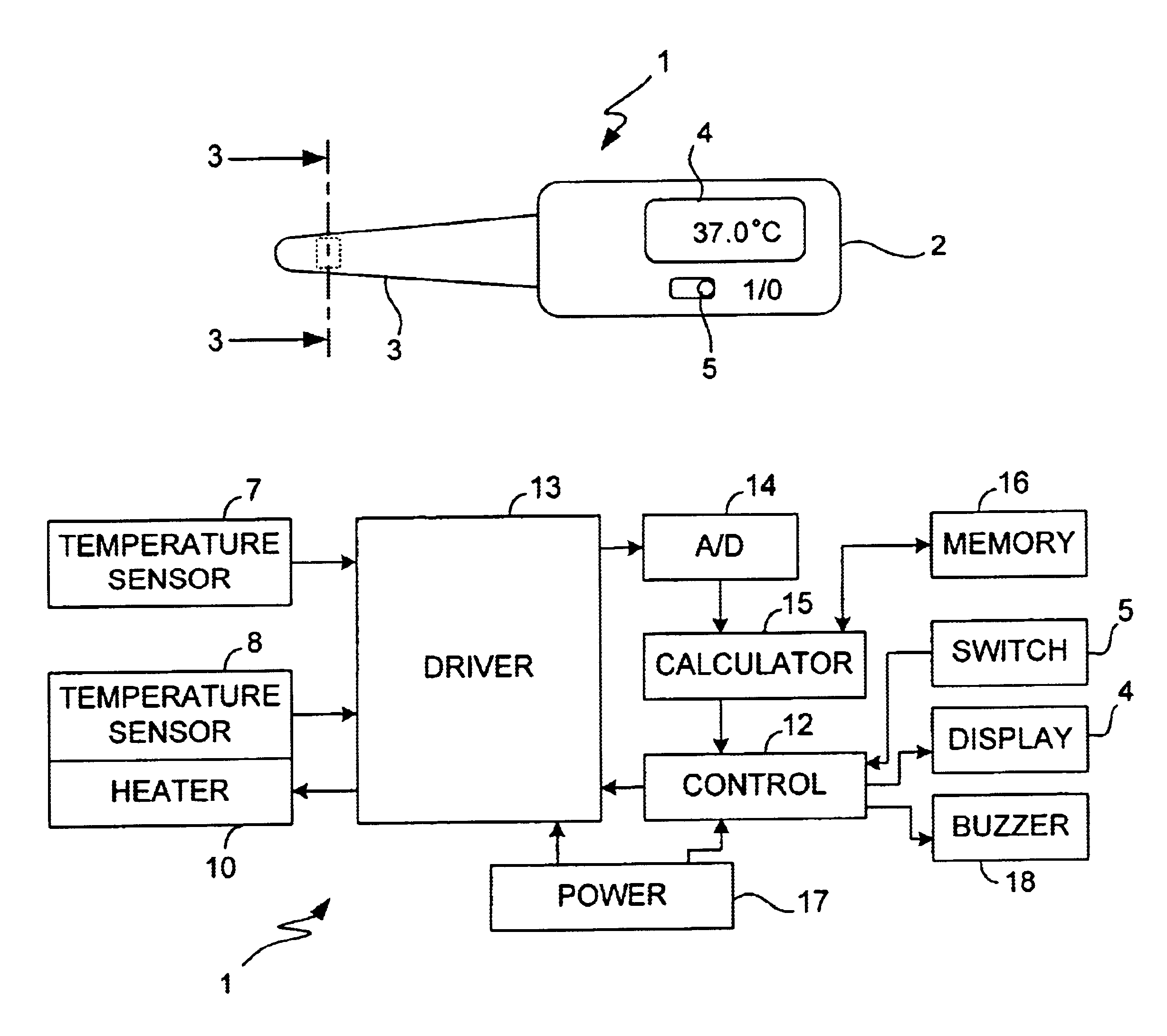
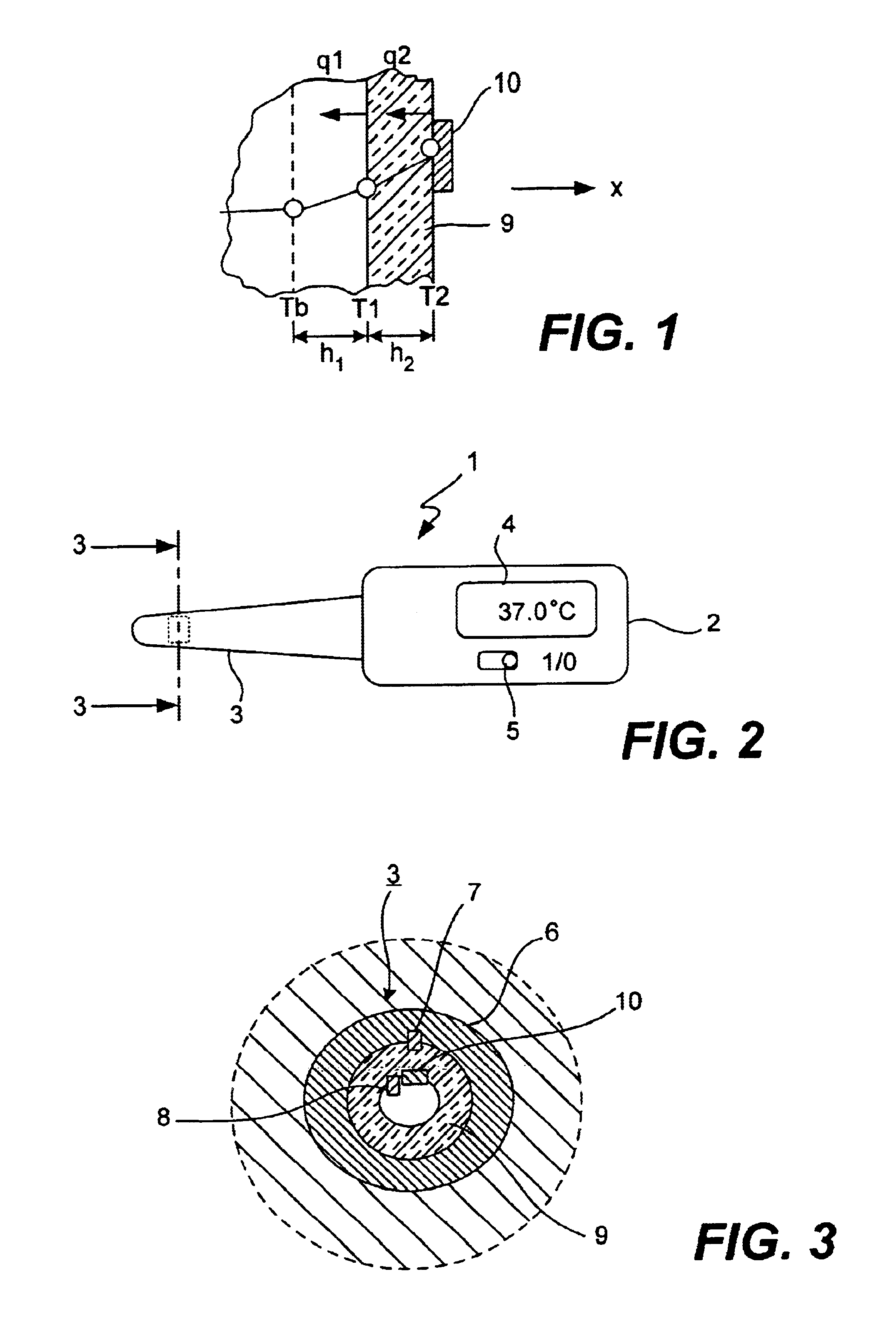
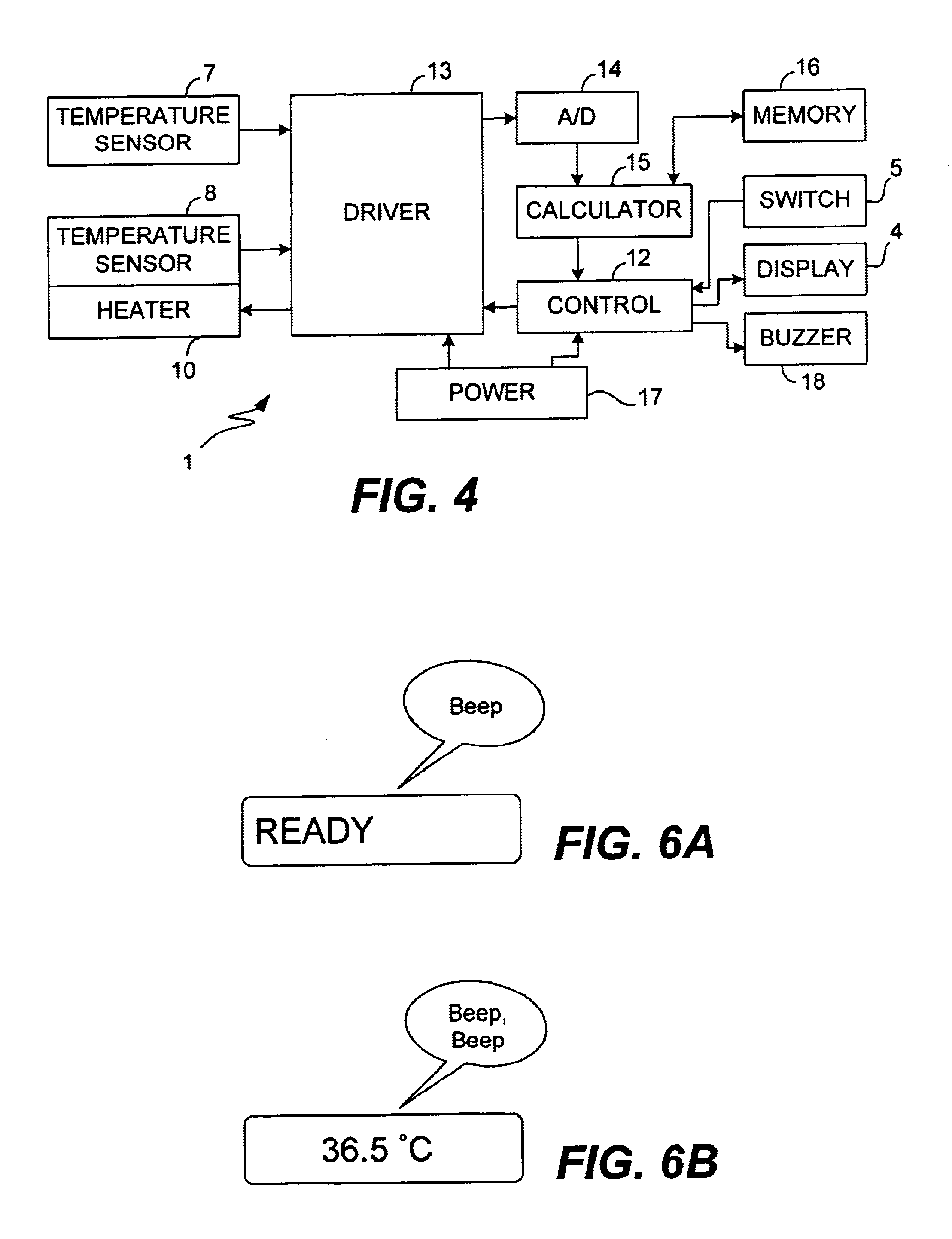
[0039]FIG. 2 shows an electronic thermometer 1 according to the invention comprising a main body 2 which is approximately in the shape of a rectangular parallelopiped and a probe 3 which protrudes longitudinally in the shape of a bar from the main body 2 such that the user may hold the main body 2 to insert the probe under an arm or under the tongue. The main body 2 contains a display device 4 such as an LCD for displaying data such as a measured value and a power switch 5. The probe 3 is approximately circular in cross-section, as shown in FIG. 3, and its outer surface is covered with a thin material 6 such as SUS having a high thermal conductivity. A temperature sensor 7 is disposed on the inner surface of this cover material 6. A variable-temperature heater 10 and a temperature sensor 8 are disposed proximally to each other on a thermally insulating member 9 on the inner surface of the cover material 6. Lead wires (not shown) connected to the temperature sensors 7 and 8 and the h...
second embodiment
[0051]FIG. 11 is referenced next to explain the principle of measurement by means of a thermometer according to this invention characterized as having two insulating members 39a and 39b having different thermal conductivities λ1 and λ2 contacting the patient's body. Let To indicate the temperature of a variable-temperature heater 10 and T1 and T2 respectively indicate the temperature at a portion of the patient's body contacting the insulating members 39a and 39b. The flux of heat flow at each of these surface positions will be indicated by q1 and q2. If the temperature is Tb inside the patient's body at a depth of h from the body surface, a one-dimensional heat transfer equation may be written as follows by keeping up to the second-order terms:
Tb=T1+(h / λb)q1+(h2 / 2αb)(dT1 / dt),
Tb=T2+(h / λb)q2+(h2 / 2αb)(dT2 / dt),
where αb and λb indicate the thermal diffusivity and the conductivity of the patient's body. Since q1=−λ1(dT1 / dt)=−λ1(T1−T0) / X and q2=−λ2(dT2 / dt)=−λ2(T2−T0) / X where X is the thic...
third embodiment
[0059]FIG. 17 is referenced next to explain the principle of measurement by means of a thermometer according to this invention characterized as determining the temperature Tb at an internal body position at a depth of h from a body surface by measuring the temperature T1 and flux of heat flow q1 at the patient's body surface opposite a variable-temperature heater 10 at temperature T0 through a thermally insulating member with thermal conductivity λ.
[0060]From the definition of heat flux, q1=−λ(dT / dt)=−λ(T1−Tb) / h, it follows that Tb=T1+(h / λ)q1. Thus, the value of Tb can be determined by measuring two or more pairs of values of q1 and T1.
[0061]Alternatively, one may start from the basic equation of heat transfer:
∂T1 / ∂t=α(∂2T1 / ∂x2)
where α is the thermal diffusivity. If the second-order term is included in its solution, this gives:
Tb=T1+(h / λ)q1+(h2 / 2α)(dT1 / dt)
since q1=−λ(dT1 / dx). This means that if three or more sets of values for T1, q1 and dT1 / dt are measured, the value of Tb can be e...
PUM
 Abstract
Description
Claims
Application Information