
Method and apparatus for vaporizing liquid chlorine containing nitrogen trichloride

a technology of liquid chlorine and nitrogen trichloride, which is applied in the direction of liquid gas reaction of thin film type, inorganic chemistry, halogen/halogen-acids, etc., can solve the problems of nitrogen trichloride, explosions, deaths, and consider nitrogen trichloride to be dangerous, so as to achieve and safe vaporization of liquid chlorin

Active Publication Date: 2012-01-26
NORAM INT
View PDF5 Cites 2 Cited by
  • Summary
  • Abstract
  • Description
  • Claims
  • Application Information

AI Technical Summary

Benefits of technology

The invention provides a way to safely evaporate a liquid chlorine stream that contains a high concentration of nitrogen trichloride. The method and apparatus prevent the formation of a churn flow regime and pool boiling, which could lead to a potential safety hazard. The process involves introducing gas into the liquid chlorine stream to force it into a flow regime that doesn't cause significant back-mixing or pool boiling. The plug-flow vaporizer can be positioned at any angle between 0.1° and 90° from the horizontal position. The gas can be any suitable gas or vapor, such as air, nitrogen, chlorine gas, hydrogen, helium, and oxygen, and mixtures thereof. The liquid chlorine feed is forced into an appropriate flow regime before it reaches the boiling zone of the vaporizer, which allows for the safe vaporization of liquid chlorine.

Problems solved by technology

The technical problem addressed in this patent text is the need for an improved method of vaporizing chlorine streams containing a high concentration of nitrogen trichloride without using organic solvents or other liquid chemicals that may cause waste streams. Existing vaporizers have limitations in dealing with liquid chlorine streams rich in nitrogen trichloride. The invention aims to provide a method for disposing of nitrogen trichloride without using a decomposer or chloroform vaporizers.

Method used


Image

  • Method and apparatus for vaporizing liquid chlorine containing nitrogen trichloride
  • Method and apparatus for vaporizing liquid chlorine containing nitrogen trichloride

Examples


first embodiment

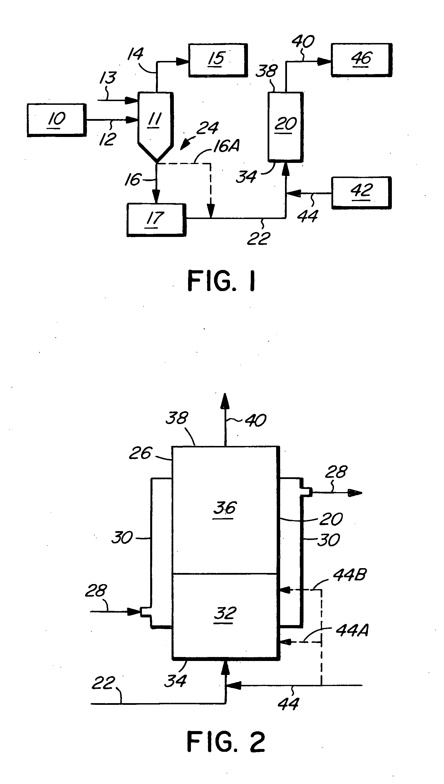
[0026]In the process of the invention, illustrated in FIG. 1, a vertical upward plug-flow vaporizer 20 receives a stream of liquid chlorine containing nitrogen trichloride (stream 22) from the chlorine production train 24 of a chloralkali plant. The production train 24 includes a chloralkali cell house 10 in which chlorine gas is produced by the electrolysis of brine. A chlorine scrubber 11 receives a stream 12 of gas chlorine from the cell house and receives a liquid chlorine stream 13. Other unit operations usually present between the chloralkali cell house 10 and the chlorine scrubber 11 are not shown in the drawings. A gas chlorine stream 14 from the scrubber is fed to a compressor 15 and is thereafter liquified. From the bottom of the chlorine scrubber 11, liquid chlorine, rich in nitrogen trichloride (stream 16), is fed to a holding tank 17, from which a stream 22 is routed to the vaporizer 20. Alternatively, the liquid chlorine, rich in nitrogen trichloride, may be fed direct...

second embodiment

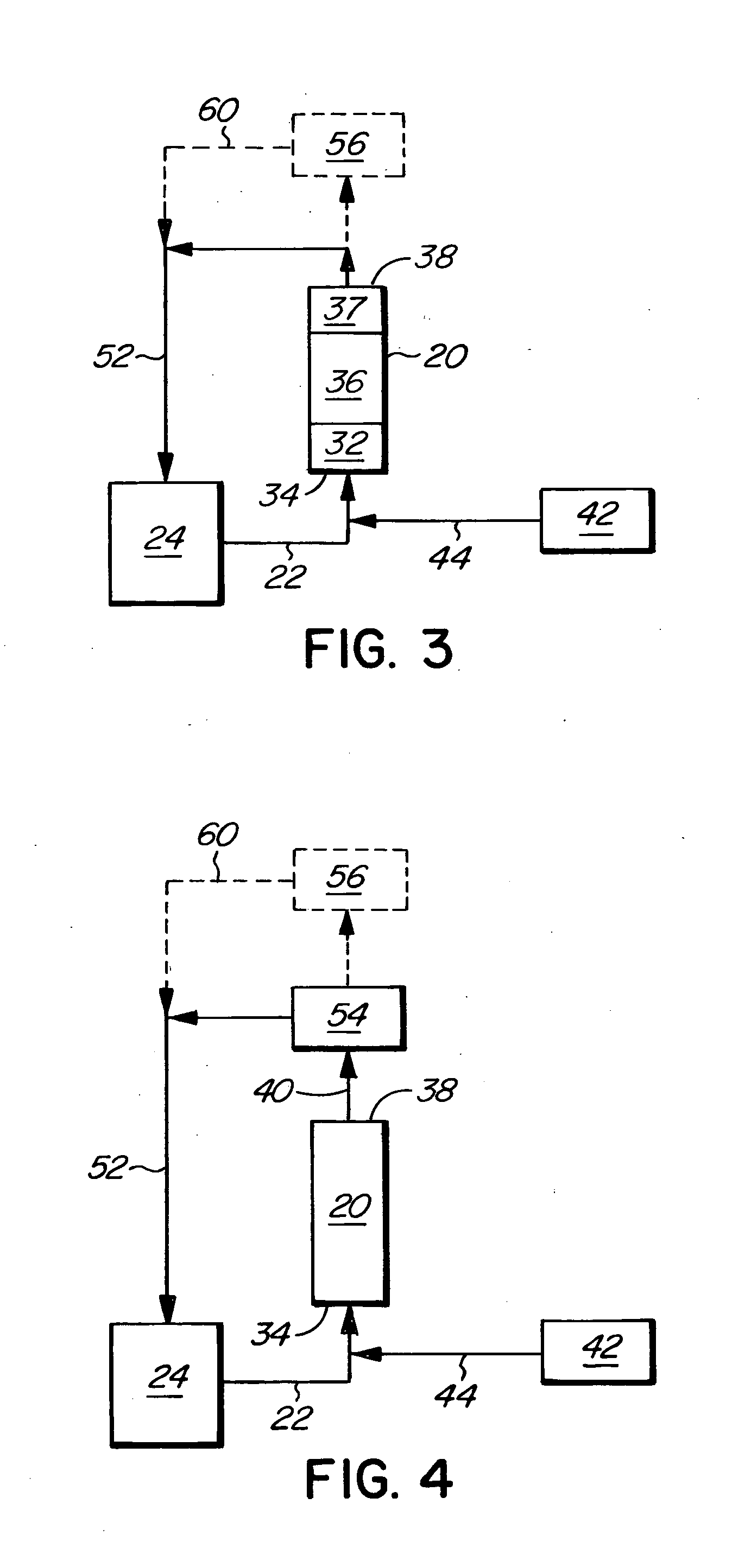
[0031]In the process of the invention, the gas mixture produced in the vaporizer 20 is routed to one or more unit operations for the destruction of nitrogen trichloride. The gas leaving the nitrogen trichloride destruction step, i.e. chlorine gas and nitrogen gas, is recycled back to the chlorine train of the chloralkali process. The invention thus avoids the generation of a waste stream or the addition of other chemicals or solvents to deal with the nitrogen trichloride. The step of destroying the nitrogen trichloride can be carried out in various ways. For example, the gas mixture evaporated in the vaporizer may be introduced into a superheater, which may be part of the vaporizer unit. This is illustrated in FIG. 3, in which the vaporizer 20 includes a superheater zone 37 downstream of the boiling zone 36. The operating conditions in the superheater are selected so as to achieve substantially complete destruction of nitrogen trichloride. The average operating temperature of the su...


PUM


Abstract

A method of safely vaporizing liquid chlorine containing high concentrations of nitrogen trichloride contaminant from a chloralkali plant. In a vertical plug-flow vaporizer having an upward flow direction, a stream of liquid chlorine containing nitrogen trichloride is received. A gas such as air, nitrogen or chlorine gas is introduced into the liquid stream upstream of the boiling zone of the vaporizer to induce a flow regime, for example annular flow or mist flow, that prevents a mass accumulation of nitrogen trichloride in the vaporizer. The liquid chlorine containing nitrogen trichloride is vaporized. The resulting gas stream may be processed to destroy the nitrogen trichloride and recycled to the chlorine production train.

Description


Claims


Application Information

Patent Timeline
Owner NORAM INT
Learn More