Device for cooling charge air

Active Publication Date: 2012-01-26
DR ING H C F PORSCHE AG
View PDF15 Cites 12 Cited by
  • Summary
  • Abstract
  • Description
  • Claims
  • Application Information

AI Technical Summary

Benefits of technology

[0013]In this way, it is firstly possible to provide a compact design of a device for cooling charge air, an

Problems solved by technology

This can result in installation space problems if charge-air coolers formed as separate assemblies are to be integrated into a motor vehicle with limited installation space.
Furthermore, if a plurality of charge-air

Method used


Image

  • Device for cooling charge air
  • Device for cooling charge air
  • Device for cooling charge air

Examples


Example

[0022]The present invention relates to a device for cooling charge air, specifically for cooling charge air which is compressed in a compressor of at least one supercharging device and which is to be supplied to an internal combustion engine, and to internal combustion engines having such a device for cooling charge air. Within the context of the present invention, the supercharging device is designed as an exhaust-gas turbocharger, scroll-type supercharger, electric supercharger or mechanical compressor.

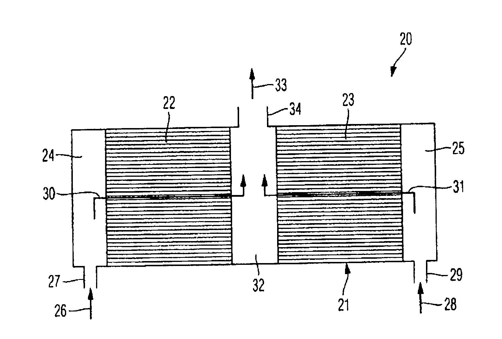
[0023]FIG. 2 shows a device 20 according to aspects of the invention for cooling charge air according to a first aspect of the present invention, wherein charge air which is compressed in a compressor of at least one exhaust-gas turbocharger and which is to be supplied to an internal combustion engine, specifically to cylinders thereof, is cooled in the device 20 shown in FIG. 2.

[0024]The device 20 according to FIG. 2 has a housing 21 in which are arranged a plurality of charge-air ...


PUM


Abstract

A device for cooling charge air, specifically for cooling charge air which is compressed in a compressor of at least one exhaust-gas turbocharger and which is to be supplied to an internal combustion engine, wherein at least two charge-air coolers are arranged in a common housing, specifically in such a way that charge air to be cooled can be supplied separately to the charge-air coolers arranged in the common housing via in each case one separate incoming-air chamber provided by the common housing, and that cooled charge air can be discharged jointly from the charge-air coolers arranged in the common housing via a common outgoing-air chamber provided by the common housing.

Description

CROSS-REFERENCE TO RELATED APPLICATION[0001]This U.S. patent application claims priority to German Patent Application DE 102010036591.2, filed Jul. 23, 2010, which is incorporated by reference herein in its entirety.FIELD OF THE INVENTION[0002]The invention relates to a device for cooling charge air. The invention also relates to a motor vehicle having a supercharged internal combustion engine.BACKGROUND OF THE INVENTION[0003]An effective measure for reducing the fuel consumption and CO2 emissions of motor vehicles has proven to be a reduction in swept volume in conjunction with supercharging of the internal combustion engine, so-called downsizing. In interaction with a direct injection of fuel, it is possible here to generate considerable potential for the reduction of fuel consumption and CO2 emissions. This is achieved in particular by means of reduced internal friction, by means of a shift of the operating point of the internal combustion engine into higher load ranges, and not ...

Claims


Application Information

Patent Timeline
IPC IPC(8): F02B29/04F28F7/00F28D15/00
CPCF02B29/0412Y02T10/146F02B29/0437Y02T10/12
Inventor LAUBE, THOMASWESSELS, MICHAEL
Owner DR ING H C F PORSCHE AG
Why Eureka
Try Eureka