Gas sensor

a technology of gas sensor and gas sensor body, which is applied in the field of gas sensor, can solve the problems of time and labor in manufacturing or assembly, and achieve the effects of reducing the thermal influence of the housing on the resin member, reducing the length of outward projection of the gas sensor from a mounting body, and improving the durability of the gas sensor

Inactive Publication Date: 2012-01-26
NGK SPARK PLUG CO LTD
View PDF8 Cites 15 Cited by
  • Summary
  • Abstract
  • Description
  • Claims
  • Application Information

AI Technical Summary

Benefits of technology

[0011]It is therefore an object of the present invention to provide a gas sensor having a structure in which a resin member radially covers a housing at least partially, wherein the length of outward projection of the gas sensor from a body to which the gas sensor is to be mounted (hereinafter, referred to as a mounting body) is shortened and thermal influence of the housing on the resin member is reduced, thereby improving durability.

Problems solved by technology

However, the cover made of metal is problematic in that, since the structure is intricate, manufacture or assembly consumes time and labor.

Method used


Image

  • Gas sensor
  • Gas sensor
  • Gas sensor

Examples


first embodiment

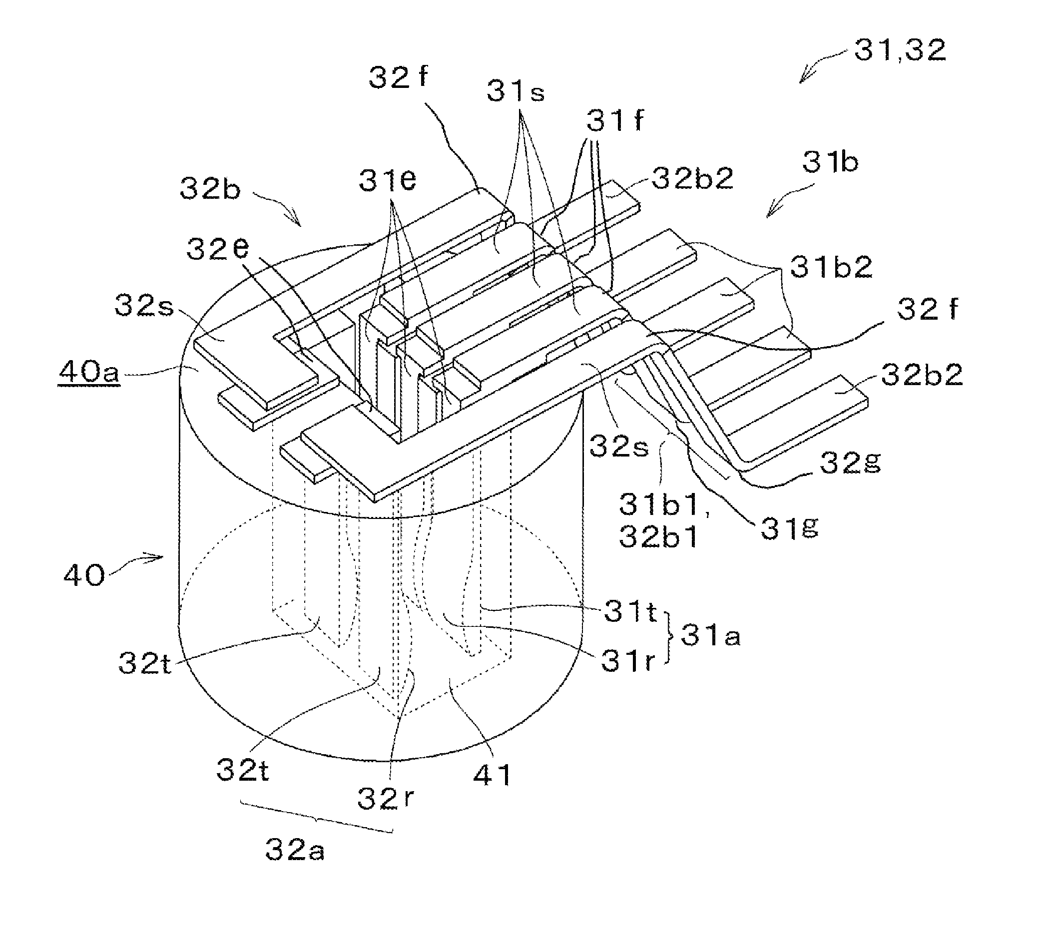
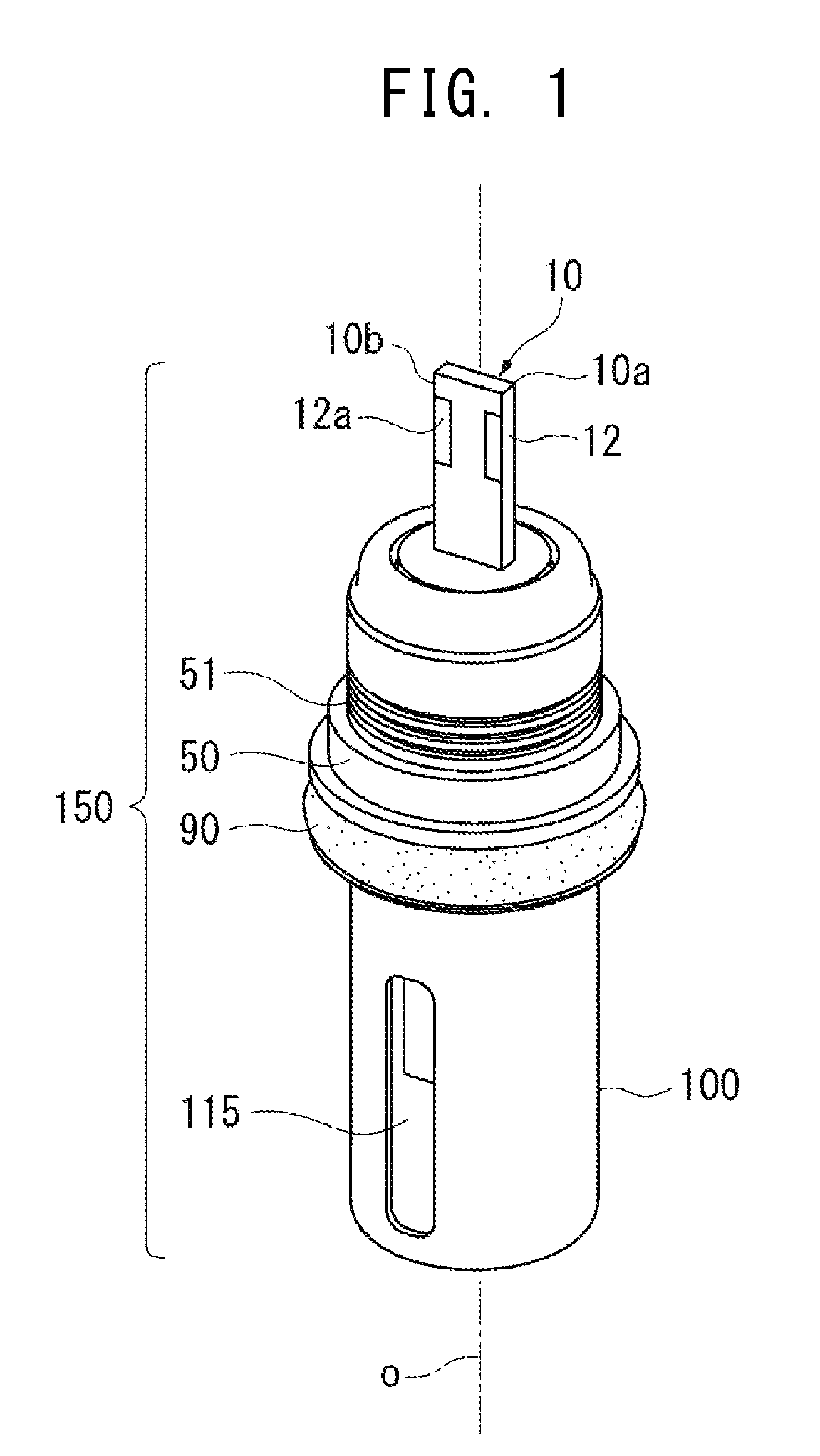
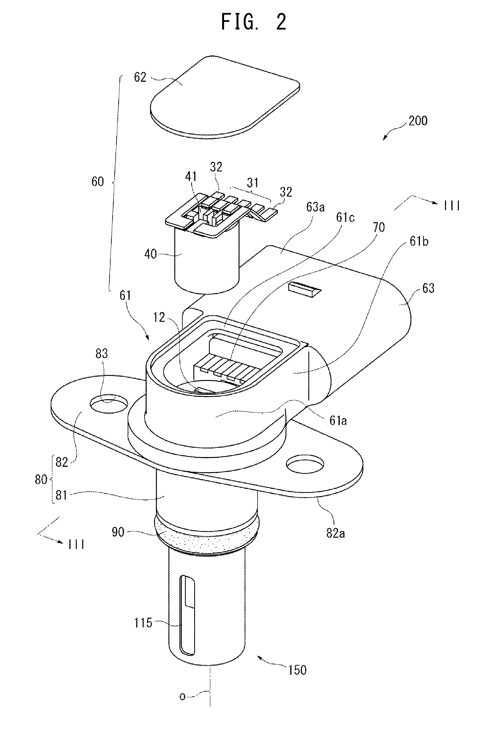
[0059]As shown in FIG. 2, the gas sensor 200 includes the element assembly 150 (including the gas sensor element 10); a resin member 60 joined to a housing 50 (see FIG. 1) of the element assembly 150; a heat sink member 80 made of metal and radially surrounding a front end portion of the resin member 60; a separator 40 made of ceramic and accommodated within the resin member 60; and connection terminals 31 and 32 attached to the separator 40. In the present first embodiment, the resin member 60 is composed of a resin member body 61 fixed to the housing 50 through insert molding, and a cover 62 fitted to the resin member body 61 from the rear side for closing the internal space of the resin member body 61. A seal member (O ring) 90 is externally fitted into a groove circumferentially formed in a front end portion of the housing 50.

[0060]As described below, the resin member body 61 of the resin member 60 is joined to the housing 50, and the cover 62 of the resin member 60 is not joine...

second embodiment

[0111]FIG. 6 is a perspective view showing an example of the schematic configuration of an element assembly 152 held within the gas sensor 210; FIG. 7 is a perspective view of the gas sensor 210 ; and FIG. 8 is a sectional view taken along line VIII-VIII of FIG. 7.

[0112]Referring to FIG. 6, the element assembly 152 is similar to the element assembly 150 of the first embodiment except for the following: the groove D2 of the housing 50 in the first embodiment is not provided, and the outer stepped subportion of the stepped portion 52e whose diameter is reduced in two steps is higher in the height of step than that of the first embodiment. Thus, the description of the element assembly 152 is omitted.

[0113]Referring to FIG. 7, the gas sensor 210 is similar to the gas sensor 200 of the first embodiment except that, in place of the O ring 90, a gasket 95 is used to provide a seal between the gas sensor 210 and the mounting body 300. Thus, repeated description of the gas sensor 210 is omit...


PUM

PropertyMeasurementUnit
widthaaaaaaaaaa
widthaaaaaaaaaa
thermal conductivityaaaaaaaaaa

Abstract

A gas sensor (200) includes a gas sensor element (10) extending in the direction of an axis O, and a housing (50) made of metal, radially surrounding the gas sensor element, and adapted for inserting at least partially into a sensor-mounting hole (350) of a mounting body (300). The gas sensor (200) further includes a resin member (60, 61) which radially surrounds the housing at least partially and having a contact portion (C) in contact with the housing that is at least partially disposed axially frontward with respect to the outer surface of the mounting body (300) around the sensor-mounting hole, and a heat sink member (80) that is in contact with the housing at an axial position the same as or located frontward of the axial position of the front end of the contact portion.

Description

BACKGROUND OF THE INVENTION[0001]1. Field of the Invention[0002]The present invention relates to a gas sensor having a gas sensor element for detecting the concentration of a particular gas.[0003]2. Description of the Related Art[0004]A gas sensor is mounted to an intake system (e.g., an intake pipe or an intake manifold) of an internal combustion engine, such as a diesel engine or a gasoline engine, in order to control, for example, the condition of combustion by monitoring the concentration of a particular gas. Conventionally, such a gas sensor has the following structure: a gas detection element is held in a housing made of metal, and various terminals, a separator, etc., provided at a proximal side (rear side) of the housing are protected with a tubular cover made of metal.[0005]However, the cover made of metal is problematic in that, since the structure is intricate, manufacture or assembly consumes time and labor. In order to cope with this problem, a structure has been develo...

Claims


Application Information

Patent Timeline
Patent Type & Authority Applications(United States)
IPC IPC(8): G01N27/407
CPCG01N27/4077G01N27/406G01N27/409G01N27/4078G01N27/407
Inventor YOSHIKAWA, TAKAYATAJIMA, TOMOHIRONISHIO, HISAHARUTSUZUKI, MASAOYONEZU, KUNIHIKO
Owner NGK SPARK PLUG CO LTD
Why Eureka
Try Eureka