Light transmission control for masking appearance of solid state light sources

a technology of light transmission control and solid-state light source, which is applied in the direction of lighting and heating apparatus, light source combinations, instruments, etc., can solve the problems of difficult heat extraction, heat retention may be an issue for a package, and optical loss may occur when the light is reflected

Active Publication Date: 2012-01-26
CREELED INC
View PDF18 Cites 83 Cited by
  • Summary
  • Abstract
  • Description
  • Claims
  • Application Information

AI Technical Summary

Benefits of technology

[0013]The present embodiments advantageously address the needs above as well as other needs by providing light emitter devices, packages, lamp systems and methods of manufacturing same. Some embodiments provide a

Problems solved by technology

While the reflective cup 513 may direct light in an upward direction, optical losses may occur when the light is reflected (i.e. some light may be absorbed by the reflector cup due to the less than 100% reflectivity of practical reflector surfaces).
In addition, heat retention may be an issue for a package, since it may be difficult to extract heat through the leads 515A, 51

Method used


Image

  • Light transmission control for masking appearance of solid state light sources
  • Light transmission control for masking appearance of solid state light sources
  • Light transmission control for masking appearance of solid state light sources

Examples


Embodiment Construction

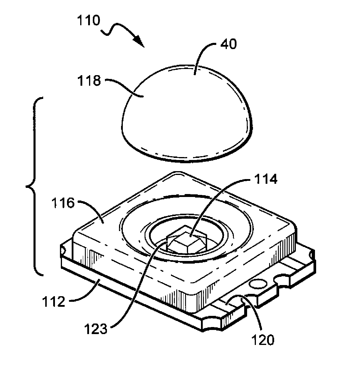
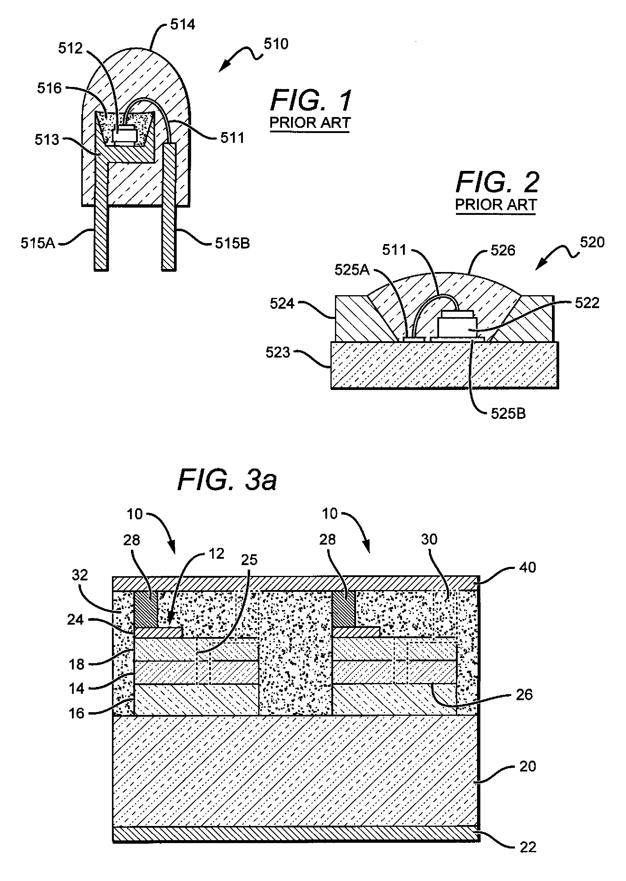
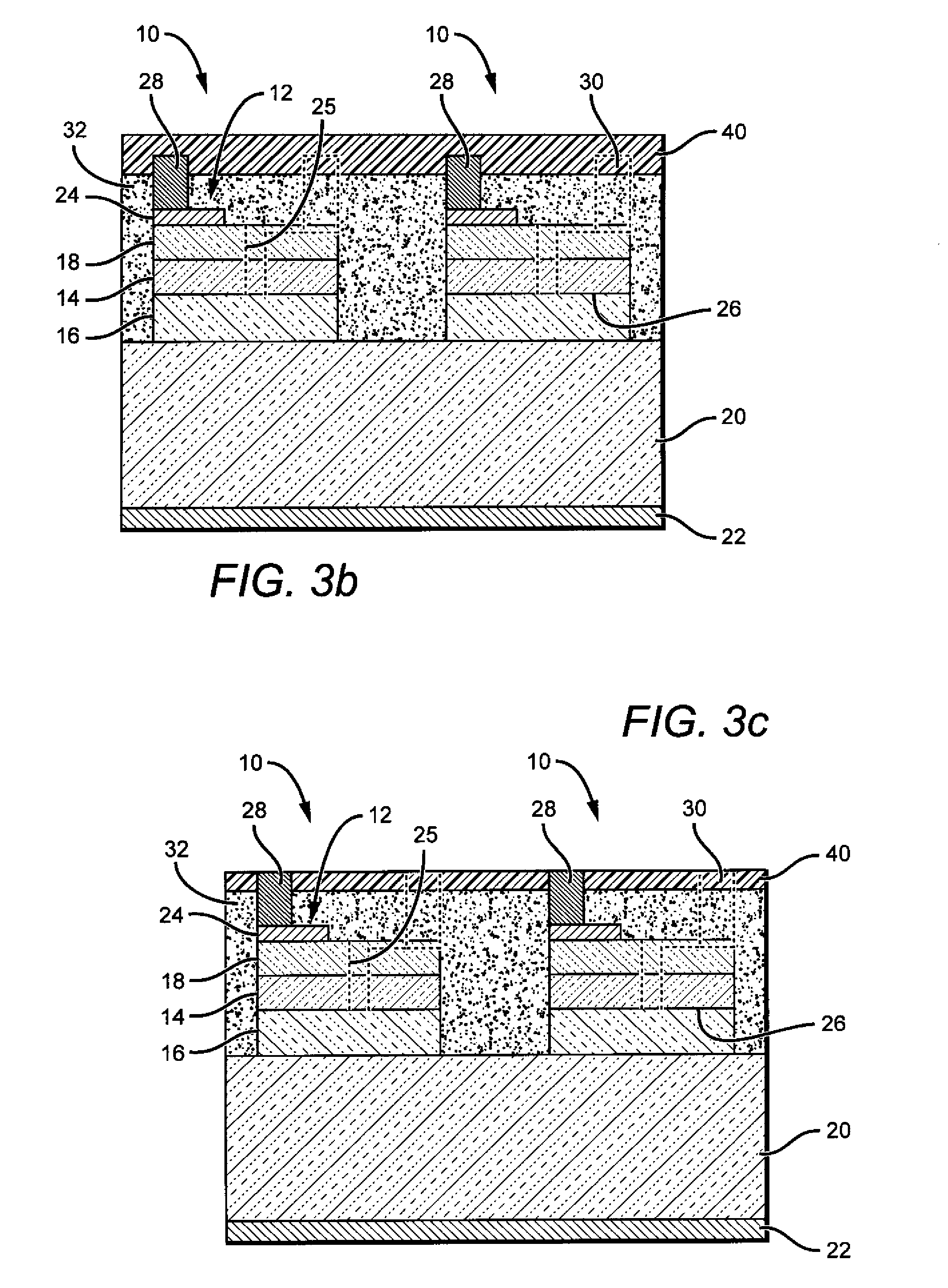
[0030]The present invention is directed to different embodiments of light emitter devices, components, and bulb structures comprising a light transmission control coating or material that can mask the visibility of these components while they are inactive, while minimizing loss of emitter performance while active. This reduces or eliminates the visibility of conversion materials on emitters or the presence of several emitters while the devices are inactive, improving the appearance of these lighting solutions. The present invention is also directed to lamp structures comprising a light transmission control coating or material that serves to mask the phosphor or conversion material from the view by the lamp user when the lamp is inactive or not energized, but also becomes clear to allow transfer of light from the lamp's light source without significant losses of efficiency such as those caused by the use of a diffuser. The present invention is also directed to methods of manufacturin...


PUM

PropertyMeasurementUnit
Fractionaaaaaaaaaa
Fractionaaaaaaaaaa
Temperatureaaaaaaaaaa

Abstract

A light emitter device, package, or lamp that comprises and light emitter and a light transmission control material to mask the appearance of at least the light emitter. In one embodiment, a light emitting diode (LED) based lamp is disclosed, comprising an LED light source. A phosphor is arranged remote to the light source such that light emitted from the light source passes through this phosphor and is converted by this phosphor. A light transmission control material is applied at least partially outside the LED light source and the phosphor to reversibly mask the appearance of the LED light source and the phosphor. The light transmission control material is less masking when the LED light source is active. A method for masking the appearance of inactive light emitters is also disclosed that comprising providing at least one light emitter. Each of the at least one light emitters is provided with a light transmission control material over the light emitters to reversibly mask the appearance of the light emitters while the light emitters are inactive. The light transmission control material is less masking when the LED light source is active.

Description

BACKGROUND OF THE INVENTION[0001]1. Field of the Invention[0002]This invention relates to light emitters and light transmission control materials to mask their appearance when inactive, and in particular to solid state emitters having light transmission control materials to mask their appearance when inactive but becoming transparent when the solid state emitter is active.[0003]2. Description of the Related Art[0004]Light emitting diodes (LED or LEDs) are solid state devices that convert electric energy to light, and generally comprise one or more active layers of semiconductor material sandwiched between oppositely doped layers. When a bias is applied across the doped layers, holes and electrons are injected into the active layer where they recombine to generate light. Light is emitted from the active layer and extracted to the surrounding ambient from all transparent surfaces of the LED.[0005]Conventional LEDs cannot generate white light from their active layers. Light from a blue...

Claims


Application Information

Patent Timeline
IPC IPC(8): H01L33/52H01L33/58H01L33/48H01L33/62
CPCF21K9/135F21V29/89F21V3/02F21V3/0481F21V14/00F21V14/003F21Y2101/02F21Y2113/005H01L25/167H01L33/44H01L33/50G02F1/0147G02F1/1334G02F1/13718H01L2224/48091H01L2224/73265F21K9/56F21V29/74F21V29/505H01L2224/45144H01L2224/16225H01L2224/32245H01L2924/00014H01L2924/00F21K9/232F21K9/64F21Y2113/13F21Y2115/10F21V3/12H01L2924/181H01L2924/00012
Inventor LOWES, THEODORE DOUGLAS
Owner CREELED INC
Why Eureka
Try Eureka