Wheel frame

a wheel frame and wheel technology, applied in the field of wheels, can solve the problems of limited range of molding techniques that could be used, and achieve the effect of greater length of axle shaft and greater strength and rigidity

Active Publication Date: 2012-01-26
ROTACASTER WHEEL
View PDF4 Cites 11 Cited by
  • Summary
  • Abstract
  • Description
  • Claims
  • Application Information

AI Technical Summary

Benefits of technology

[0013]The mouth may be wholly or partially cylindrical and / or wholly or partially conical in internal and external shape. Similarly, the axle shall may be uniformly cylindrical or may be frusto-conical in shape. The axle shaft may he partly conical in shape, particularly proximal to its free end. Accordingly, the axle shaft and mouth may each be molded in a die component defining a cylindrical or conical structure, or a combination of both. This enables the axle shaft and mouth to be formed in a single die component defining a cylindrical or conical cavity that completely surrounds the component to be formed. This die arrangement may have the effect that no mold parting lines extending longitudinally are formed on the axle shaft and mouth components so these components, having a closely circular cross-section at any point along their length, may be formed to have a round cross-section to a high degree of accuracy. This enables the axle shaft to mouth components to be uniformly and consistently molded accurately round without blemishes and shape inconsistencies, enabling manufacturing to low tolerances with resultant minimal play between moving parts.
[0017]The axle shaft may terminate in a free end that is the same radius as the remainder of the axle shaft. That is, the axle shaft has a consistently round cross-section throughout its length. Alternatively, the axle shaft may include a stepped terminating portion that has a smaller or larger radius than the main body of the axle shaft. The terminating portion may be sized and configured to be received in the mouth. Accordingly, the radius of the mouth bore may be smaller than the radius of the main body of the axle shaft and the external cylindrical or conical wall of the mouth may have a greater diameter than the diameter of the axle shaft main body at the juncture. In this way, the mouth may perform as an annular shoulder effective to retain a roller on the axle shaft between the head of the peripheral axle on which the roller is mounted and the head of an adjacent peripheral axle.
[0018]The mouth bore may be a through-bore extending through from the mouth to an open end at the back of the head. The through-bore may be effective to permit the terminal end of the axle shaft to be in contact with an over-molded support of the wheel body. The through-bore may thus provide an opening into which the over-molded wheel body may extend during the molding process to reinforce the connection between the axle shaft and the head to provide the combined structure of the axles and the over-molded wheel body that is of greater strength and rigidity than if the over-molding did not so extend into the interstitial spaces of the axle head. The terminal end butt of the axle shaft may be shaped at an angle transverse to the longitudinal axis of the axle shaft to permit a greater length of axle shaft to be inserted into the mouth bore while conforming to the corner portion shape. The joint between the axle shaft and the head of an adjacent peripheral axle may be further strengthened by adhesive, heat fusion, ultrasonic or other known joining or welding techniques.
[0019]The wheel preferably further comprises a wheel body or frame. The wheel body may include a hub or central aperture defining a main axle or central bore. Extending from the hub or an inner rim of the wheel body may be a plurality of outwardly extending supports. The outwardly extending supports may extend radially from the center of the wheel body. The outer ends of the supports may secure the heads. Preferably, the wheel body is formed at least partially around the heads. The heads may be mounted on or in the outwardly extending supports. The outwardly extending supports may partially or wholly surround the heads, provided that the supports do not interfere with the movement of the rollers.
[0024]The bushings may be shaped to follow the contours of the roller tyre. For example, the external surface of the bushing may have a plurality or annular ribs aligned laterally relative to the bushing's longitudinal axis to better grip the tyre (preferably over-molded) and be effective against longitudinal slippage or movement of the tyre relative to the bushing. Preferably, however, the external surface has a plurality of longitudinal ribs. Advantageously, the longitudinal ribs are arc or bow shaped to follow the general cigar shape of the roller's external shape. The arched ribs are preferably solid and integral to the general cylindrical core of the bushing throughout their lengths, although they may be supported only at their ends and bowed in the middle. Longitudinally aligned ribs will reduce relative movement between the ribs and the tyre as the roller rolls about its longitudinal roller axis, strengthening the joint and extending the life of the roller.
[0033]The head may further include spurs, ridges or other surface features that permit greater adherence to a structure molded about the head or a segment thereof. The spur or other surface features may serve to increase the surface area between the adhering wheel body and the receiving head thereby strengthening and reinforcing the joint and increasing the strength and rigidity of the wheel structure.

Problems solved by technology

The frame included an integrally formed polyaxled ring that required the rollers to be molded over the axles and limited the range of molding techniques that could be utilized.

Method used


Image

  • Wheel frame
  • Wheel frame
  • Wheel frame

Examples


Embodiment Construction

[0062]Preferred features of the present invention will now be described with particular reference to the accompanying drawings. However, it is to be understood that the features illustrated in and described with reference to the drawings are not to be construed as limiting on the scope of the invention.

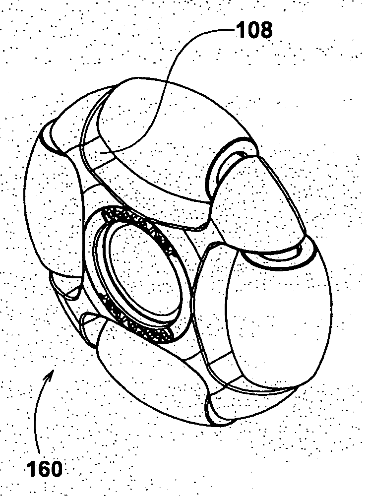
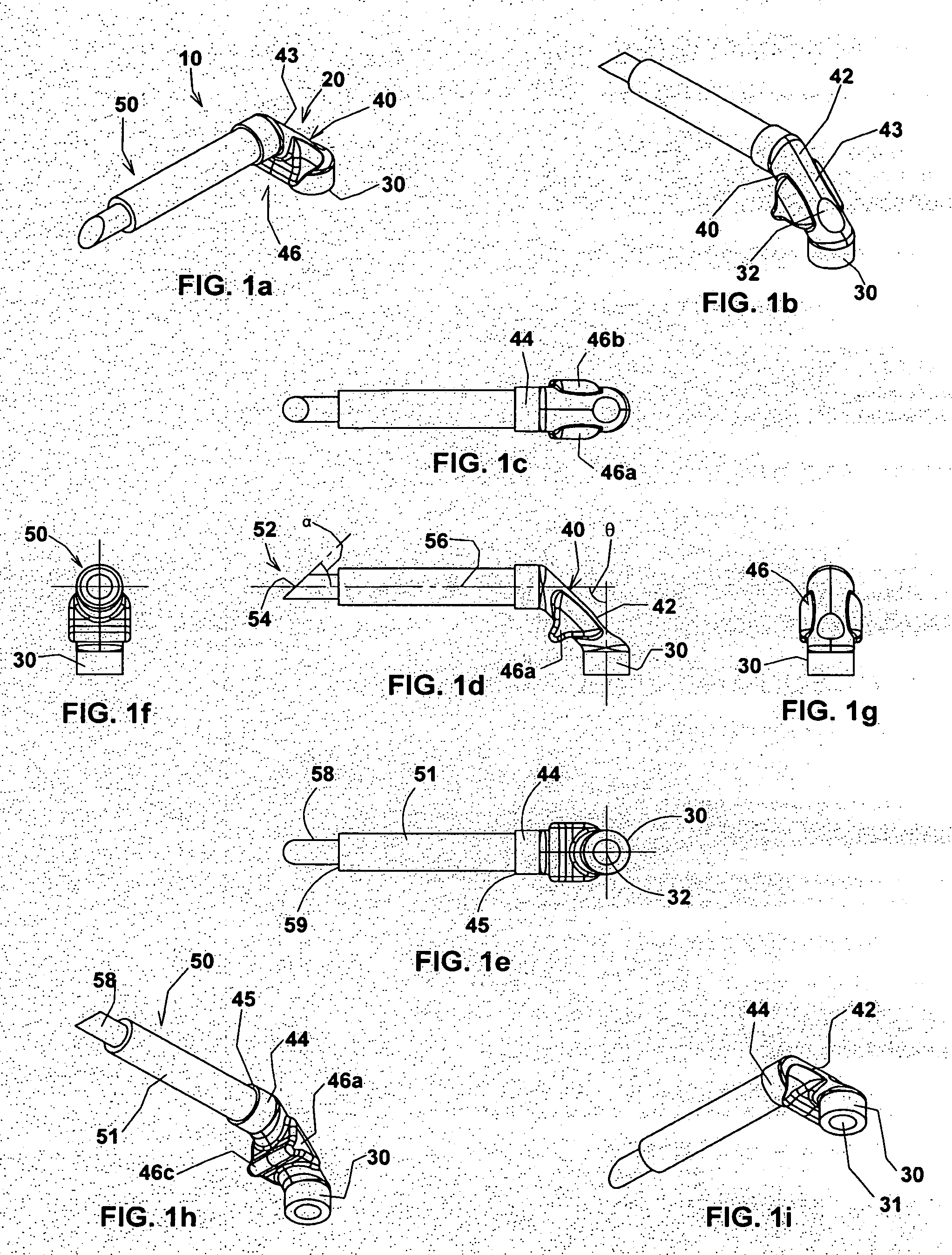
[0063]Referring to FIGS. 1a to 1i, there is shown a peripheral axle 10 comprising a head 20 and an axle shaft 50. The peripheral axle 10 shown is one of four peripheral axles 10 shaped to form a continuous ring 80 (see below) with three other like peripheral axles 10. However, the skilled person will appreciate that the continuous ring 80 may be configured to comprise a lesser or greater number of peripheral axles, for example between three and ten axles making up the continuous ring of a wheel (see below). In each case, the peripheral axle 10 components may be identical, having a male end (the axle shaft 50) and a female end (the head 20), so that each peripheral axle 10 mar mate wit...


PUM

PropertyMeasurementUnit
angleaaaaaaaaaa
angleaaaaaaaaaa
corner angleaaaaaaaaaa

Abstract

A method of assembling a wheel rotatable about a main axis and having a plurality of peripheral rollers mounted on peripheral axles aligned tangentially about the wheel and radially spaced from the main axis, each peripheral axle joined to adjacent other peripheral axles to form a continuous ring comprising the peripheral axles, the method including the steps of: molding each peripheral axle in a die having a cylindrical cycle for forming the axle shaft of the peripheral axle without longitudinal separation tines, the peripheral axles each having a receiving head portion for receiving a free end of the axle shaft of an adjacent peripheral axle; mounting a roller on each axle shaft; joining the peripheral axles together to form a continuous ring of peripheral axles; and molding a wheel body including a support structure around the continuous ring.

Description

CROSS-REFERENCE TO RELATED APPLICATION[0001]This is a national phase entry under 35 U.S.C. §371 of International Patent Application PCT / AU2010 / 001419, filed Oct. 25, 2010, published in English as International Patent Publication WO 2011 / 047443 A1 on Apr. 28, 2011, which claims the benefit under Article 8 of the Patent Cooperation Treaty to Australian Patent Application Serial No. 2009905168, filed Oct. 23, 2009.TECHNICAL FIELD[0002]This invention relates to a wheel. More particularly, this invention relates to a wheel frame. Still more particularly, this invention relates to a wheel frame for a wheel having a plurality of peripheral rollers capable of rotating about peripheral axes aligned normal to the main axis of rotation of the wheel.BACKGROUND[0003]The following references to, and descriptions of, prior proposals or products are not intended to be, and are not to be construed as, statements or admissions of common general knowledge in the art. In particular, the following prior...

Claims


Application Information

Patent Timeline
Patent Type & Authority Applications(United States)
IPC IPC(8): B60B19/12B23P17/00
CPCB60B19/12Y10T29/49481B60B33/0028B60B33/0039B60B33/0049B60B2200/40B60B2200/432B60B2310/204B60B2310/316B60B2360/32B60B2380/14B60B2380/50B60B2900/351B62B2301/02B60B19/003
Inventor MCKINNON, PETER R.TAYLOR, GERRY
Owner ROTACASTER WHEEL
Why Eureka
Try Eureka