Eddy current detection

a detection technology and current technology, applied in the direction of magnetic property measurement, material magnetic variables, instruments, etc., can solve the problems of material defects (or flaws), inclusions and corrosion, defects may form,

Active Publication Date: 2012-01-26
RADIATION MONITORING DEVICES
View PDF14 Cites 85 Cited by
  • Summary
  • Abstract
  • Description
  • Claims
  • Application Information

AI Technical Summary

Benefits of technology

[0017]In one aspect, an eddy current probe is provided. The probe includes a first substrate having a substantially planar surface and a drive coil disposed on the substantially planar surface of the first substrate. The probe includes a second substrate smaller than the first substrate. The second substrate has a substantially planar surface. The probe includes an anisotropic magnetoresistive (AMR) sensor disposed on the substantially planar surface of the second substrate and attached to the first substrate within a perimeter of the drive coil. The probe further includes a detection loop comprising a first electrical lead and a second electrical lead. The first electrical lead is connected to a first end of the AMR sensor and the second electrical lead is connected to a second end of the AMR sensor. The first electrical lead and second electrical lead are positioned at least partially around the first substrate to form the detection loop. The detection loop is substantially perpendicular to the drive coil.
[0018]In one aspect, an eddy current detection probe is provided. The probe includes a drive coil and a conductive detection loop oriented substantially perpendicular to the drive coil. The conductive detection loop has a height that is substantially perpendicular to the drive coil and less than 2.5 mm. In some embodiments, the conductive detection loop has a height that is less than 0.5 mm.

Problems solved by technology

In general, materials may have defects (or flaws) in them, such as cracks, inclusions and corrosion.
The defects may form for various reasons, including as a result of manufacturing and / or stresses experienced by the material over its lifetime.
The distributions of the eddy currents will be altered by cracks (or other defects) in the material, thus creating perturbations in the induced magnetic fields.
Thus, when an AMR sensor is placed in the presence of an eddy current, the magnetic fields generated by the eddy current may alter the resistance value of the AMR sensor.

Method used


Image

  • Eddy current detection
  • Eddy current detection
  • Eddy current detection

Examples


Embodiment Construction

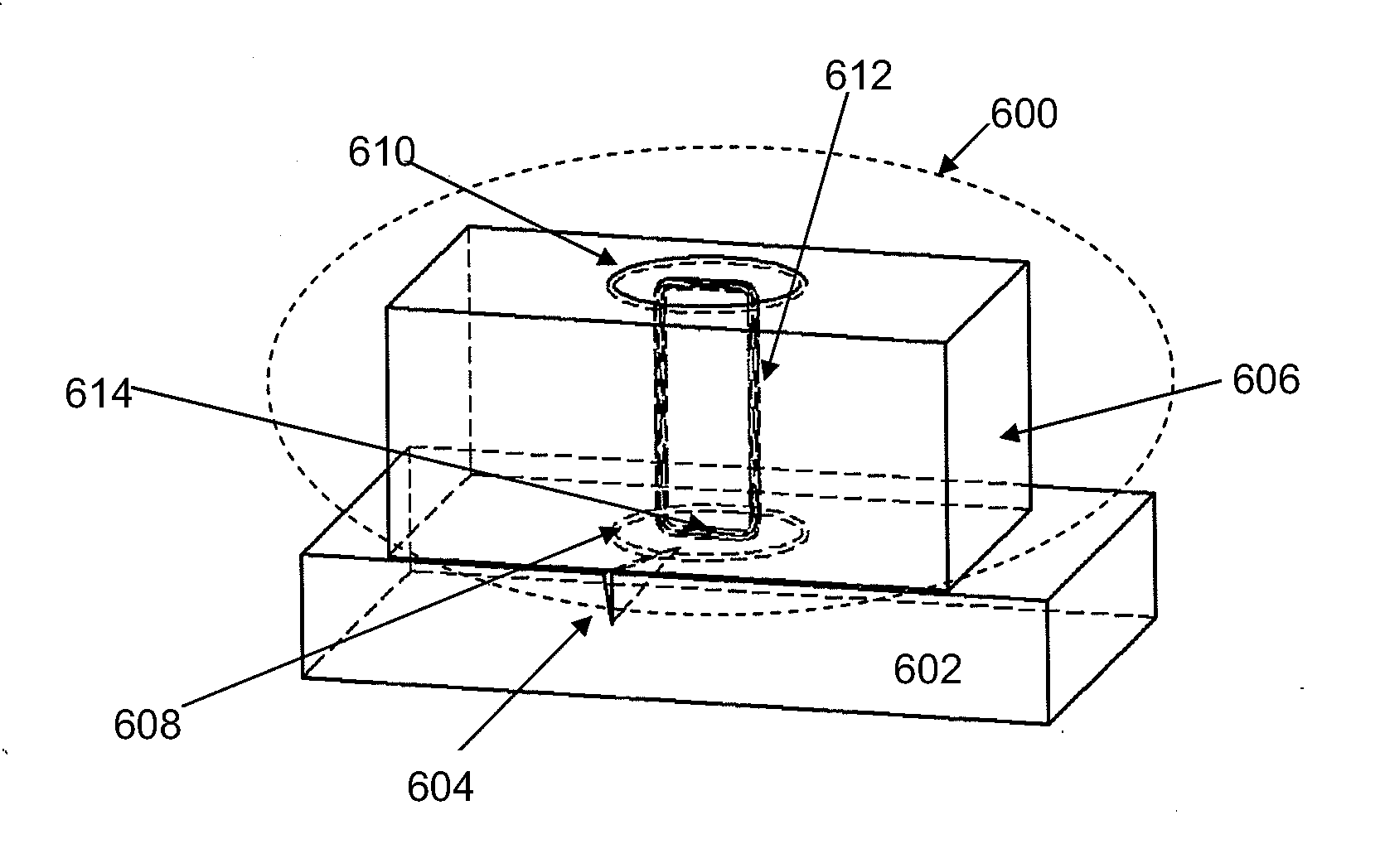
[0036]The inventors have appreciated that conventional eddy current probes are not without drawbacks in at least some operating scenarios. For example, a problem with conventional coil-based eddy current probes is that, as described above, the orientation of the detection coil is such that the detection coil is sensitive to the magnetic fields directly generated by the drive coil. Because the magnetic fields generated by the drive coil are typically much larger than the magnetic field disturbances associated with cracks (or other defects) in a material under test, conventional coil-based eddy current probes may have difficulty in detecting such cracks (or other defects). Also, in the case of conventional single-coil based eddy current probes (i.e., an eddy current probe using a combination drive / detection coil), the design parameters of the detection circuit cannot be optimized independently of the parameters of the drive circuit.

[0037]The use of an AMR sensor may address some probl...


PUM

PropertyMeasurementUnit
heightaaaaaaaaaa
areaaaaaaaaaaa
frequencyaaaaaaaaaa

Abstract

Eddy current detection probes and related methods are disclosed. In some embodiments, the eddy current detection probes are hybrid probes, including a solid state sensor and a detection loop. In some embodiments, the eddy current detection probes include a drive coil and a detection loop, with the detection loop having a sensitive axis that is not parallel to principal axis of the drive coil. In some such embodiments, the sensitive axis of the detection loop is perpendicular to the principal axis of the drive coil.

Description

RELATED APPLICATIONS[0001]The present application claims the benefit under 35 U.S.C. 119(e) to U.S. Provisional Patent Application Ser. No. 61 / 367,648, filed on Jul. 26, 2010 under Attorney Docket No. D0701.70002US00 and entitled “Eddy Current Detection”, which is incorporated herein by reference in its entirety.BACKGROUND[0002]1. Field[0003]The present application discloses various aspects relating to eddy current detection technology.[0004]2. Related Art[0005]In general, materials may have defects (or flaws) in them, such as cracks, inclusions and corrosion. The defects may form for various reasons, including as a result of manufacturing and / or stresses experienced by the material over its lifetime.[0006]One manner for detecting such defects in a conductive material (such as a metal or metal alloy) is to generate eddy currents within the material and detect the resulting magnetic fields. Eddy currents are generated in a conductive material in response to a suitable time varying ma...

Claims


Application Information

Patent Timeline
Patent Type & Authority Applications(United States)
IPC IPC(8): G01N27/72G01R33/09B32B38/14
CPCG01N27/9033G01R33/096G01R33/09G01N27/9006G01B1/00G01B2210/00G01N1/00G01N2201/00G01R1/00
Inventor TIERNAN, TIMOTHY C.STEINBACK, MARKRENSING, NOA M.WESTSTRATE, EVAN
Owner RADIATION MONITORING DEVICES
Why Eureka
Try Eureka