Eddy current testing method and eddy current testing apparatus

a technology of eddy current testing and testing apparatus, which is applied in the direction of measuring devices, instruments, scientific instruments, etc., can solve the problems of position accuracy and achieve the effects of reducing detection noise, and small amount of detection nois

Inactive Publication Date: 2009-04-23
HITACHI-GE NUCLEAR ENERGY LTD
View PDF6 Cites 16 Cited by
  • Summary
  • Abstract
  • Description
  • Claims
  • Application Information

AI Technical Summary

Benefits of technology

[0010]With the above-mentioned conventional technique, voltages applied to the excitation coils 3A and 3B have the same amplitude (in other words, excitation currents have the sample amplitude), and the detection coil 4 is disposed on the symmetry axis L between the excitation coils 3A and 3B, thus balancing out the bypass currents in two different circumferential directions at the detection position of the detection coil 4 and reducing detection noise caused by the deformed portion 1c of the heat exchanger tube 1 and the tube sheet 2. However, since there is a limit in the positional accuracy of the detection coil 4 for a reason of manufacture, the bypass currents in different circumferential directions slightly become off-balance at the detection position of the detection coil 4, resulting in a very small amount of detection noise. Even with a high positional accuracy of the detection coil 4, if the distance (liftoff) between the excitation coil 3A and the inspection surface of the heat exchanger tube 1 differs from the distance between the excitation coil 3B and the inspection surface, the magnitude of the eddy current by the excitation coil 3A will differ from the magnitude of the eddy current by the excitation coil 3B, and the bypass currents in different circumferential directions slightly become off-balance at the detection position of the detection coil 4, resulting in a very small amount of detection noise. Therefore, there has been a room for the reduction of detection noise, that is, the improvement in the SN ratio.
[0011]An object of the present invention is to provide an eddy current testing method and an eddy current testing apparatus that can reduce detection noise to increase the SN ratio thus improving the defect detection accuracy.
[0012]In order to attain the above-mentioned object, the present invention provides an eddy current testing apparatus which includes an eddy current testing sensor comprising: a pair of excitation coils disposed such that each of their axial directions becomes approximately perpendicular to the inspection surface of a subject, being spaced from each other in the coil radial direction, to induce an eddy current in the subject; and a detection coil disposed between the pair of excitation coils so that its axial direction becomes approximately in parallel with the inspection surface of the subject and approximately perpendicular to a straight line connecting the centers of the excitation coils to detect a change of the eddy current induced in the subject; wherein the eddy current testing apparatus includes excitation voltage control means for applying voltages having different amplitudes to the pair of excitation coils so as to reduce detection noise of the detection coil.
[0013]In accordance with the present invention, detection noise can be reduced to increase the SN ratio thus improving the defect detection accuracy.

Problems solved by technology

However, since there is a limit in the positional accuracy of the detection coil 4 for a reason of manufacture, the bypass currents in different circumferential directions slightly become off-balance at the detection position of the detection coil 4, resulting in a very small amount of detection noise.

Method used


Image

  • Eddy current testing method and eddy current testing apparatus
  • Eddy current testing method and eddy current testing apparatus
  • Eddy current testing method and eddy current testing apparatus

Examples


Embodiment Construction

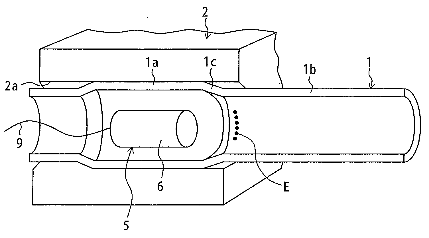
[0034]An embodiment of a first aspect of the present invention will be explained below with reference to FIGS. 1 to 5. The present embodiment is intended for inspection of the heat exchanger tube 1 of the above-mentioned heat exchanger. The same symbols are assigned to elements equivalent to those mentioned above, and similar explanations will not be duplicated.

[0035]FIG. 1 is a diagram showing an eddy current testing sensor according to the present embodiment, together with the cross-sectional structure of the heat exchanger tube 1.

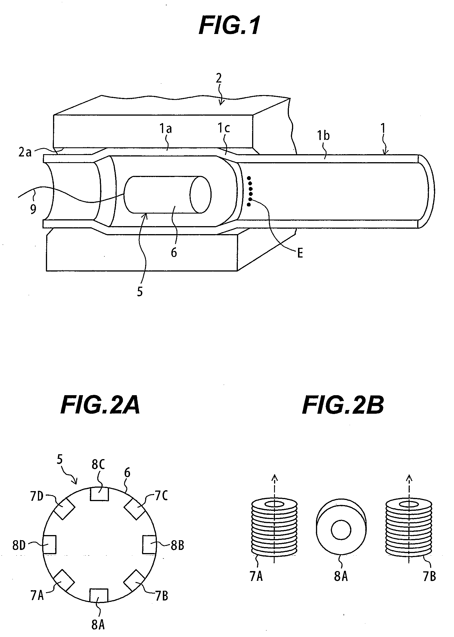
[0036]FIG. 2A is a sectional view showing the circular structure of the eddy current testing sensor, and FIG. 2B is a fragmentally enlarged view showing the disposing directions of excitation coils and a detection coil of FIG. 2A.

[0037]Referring to FIGS. 1, 2A, and 2B, an eddy current testing sensor 5 includes a cylindrical main unit case 6 that can be inserted into the heat exchanger tube 1, four excitation coils 7A to 7D circumferentially disposed at e...


PUM

PropertyMeasurementUnit
axial eddy currentaaaaaaaaaa
radial thicknessaaaaaaaaaa

Abstract

The present invention provides an eddy current testing method and an eddy current testing apparatus that can reduce detection noise to increase the SN ratio thus improving the defect detection accuracy.An eddy current testing sensor includes a pair of excitation coils and a detection coil disposed therebetween. For example, a voltage regulator applies voltages having different amplitudes to the pair of excitation coils so as to reduce detection noise caused by a deformed portion of a heat exchanger tube and a tube plate in a detection signal of the detection coil. Alternatively, for example, an eddy current testing detector applies a first excitation frequency f1, at which tube material noise is reduced to negligible an amplitude, and a second excitation frequency f2, which is higher than the first excitation frequency f1, to the eddy current testing sensor. The phase and gain of a measurement waveform with the second excitation frequency f2 are adjusted and then a differential waveform of the first and second excitation frequencies f1 and f2 is obtained based on an induction voltage detected by the detection coil so as to cancel out tube expansion noise.

Description

BACKGROUND OF THE INVENTION[0001]1. Field of the Invention[0002]The present invention relates to an eddy current testing (ECT) method and an eddy current testing apparatus. More particularly, the present invention relates to an eddy current testing method and an eddy current testing apparatus suitably used for eddy current testing of a tube expansion of heat exchanger tubes of a heat exchanger of a power plant.[0003]2. Description of the Related Art[0004]For example, a heat exchanger tube of a heat exchanger installed in a clean up water system of a nuclear plant is subjected to periodical maintenance and inspection in order to check whether a crack or other defect has occurred. The heat exchanger tube of the heat exchanger is formed, for example, in U shape. Both ends of the heat exchanger tube are inserted into penetration holes of a tube sheet (magnetic material). For details, as shown in FIG. 6, a heat exchanger tube 1 is pressed from the inside so as to expand the tube diameter...

Claims


Application Information

Patent Timeline
Patent Type & Authority Applications(United States)
IPC IPC(8): G01N27/90
CPCG01N27/90
Inventor NARISHIGE, SOSHINISHIMIZU, AKIRAKOIKE, MASAHIROABE, YOSHIHARUNARUMI, YUICHI
Owner HITACHI-GE NUCLEAR ENERGY LTD
Why Eureka
Try Eureka