Expansion card mounting assembly

Inactive Publication Date: 2012-01-26
HONG FU JIN PRECISION IND (SHENZHEN) CO LTD +1
View PDF13 Cites 17 Cited by
  • Summary
  • Abstract
  • Description
  • Claims
  • Application Information

AI Technical Summary

Problems solved by technology

However, such securing means often utilize fasteners or fasteners to secure the

Method used


Image

  • Expansion card mounting assembly
  • Expansion card mounting assembly
  • Expansion card mounting assembly

Examples


Embodiment Construction

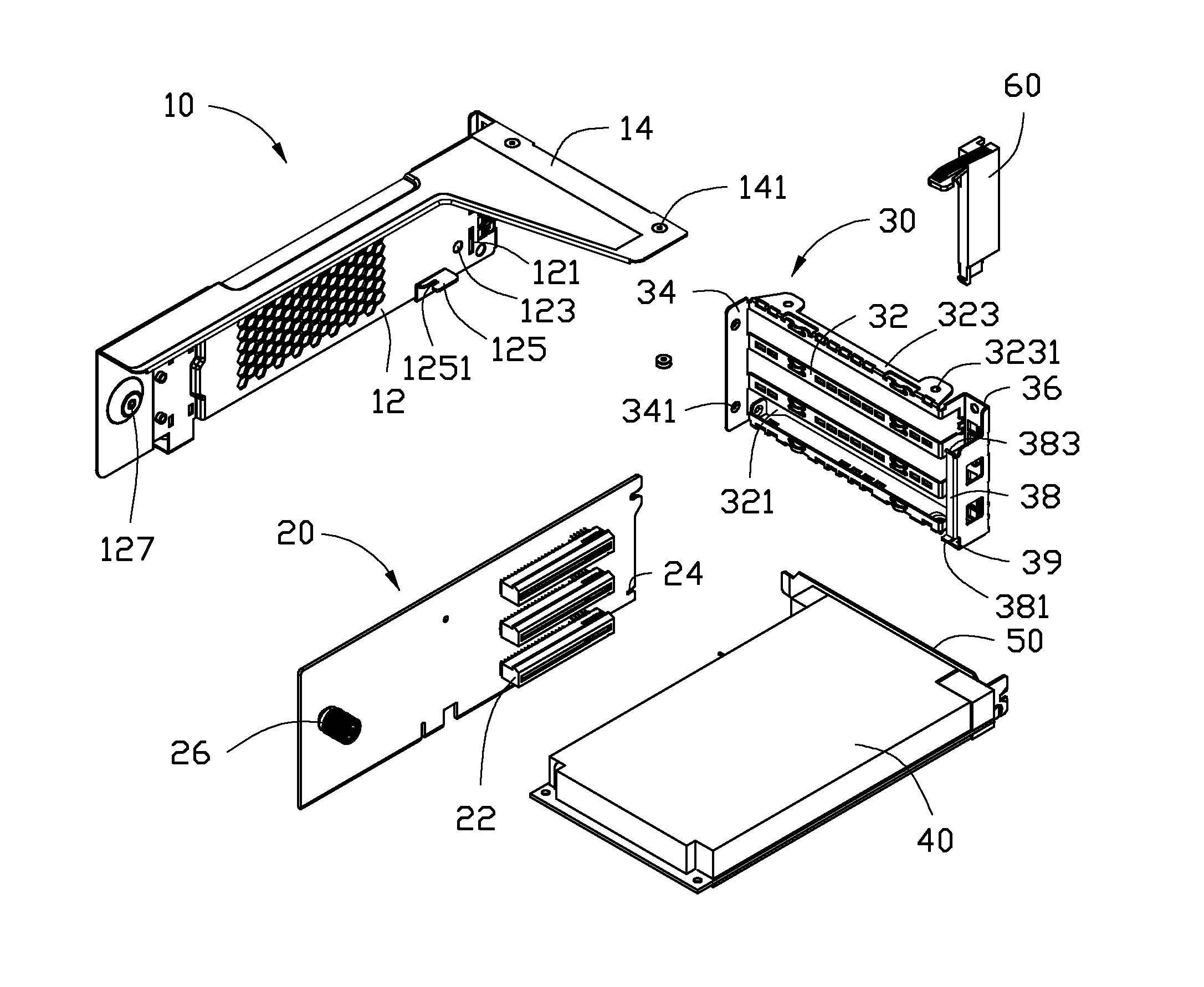
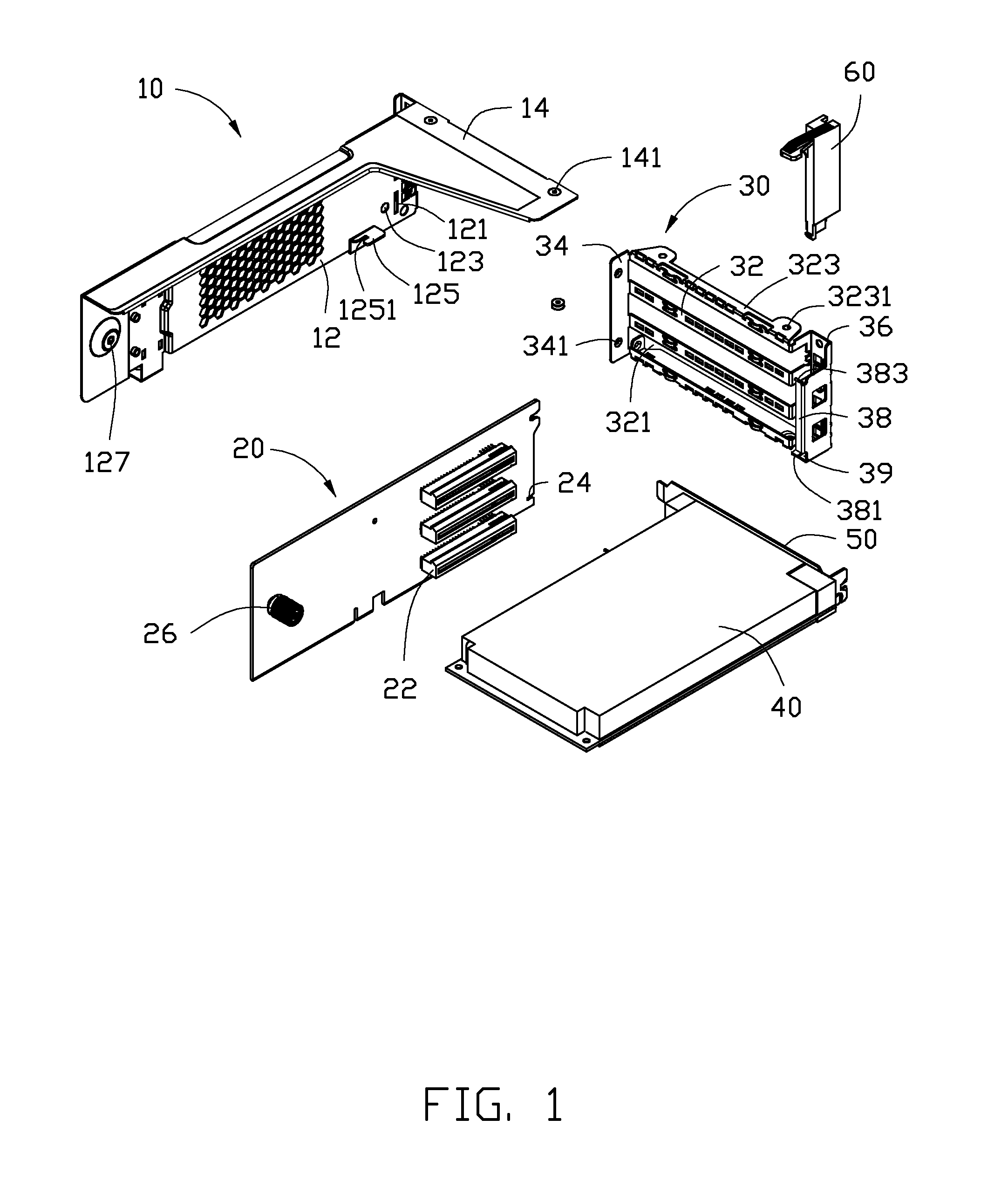
[0012]The disclosure is illustrated by way of example and not by way of limitation in the figures of the accompanying drawings in which like references indicate similar elements. It should be noted that references to “an” or “one” embodiment in this disclosure are not necessarily to the same embodiment, and such references mean at least one.

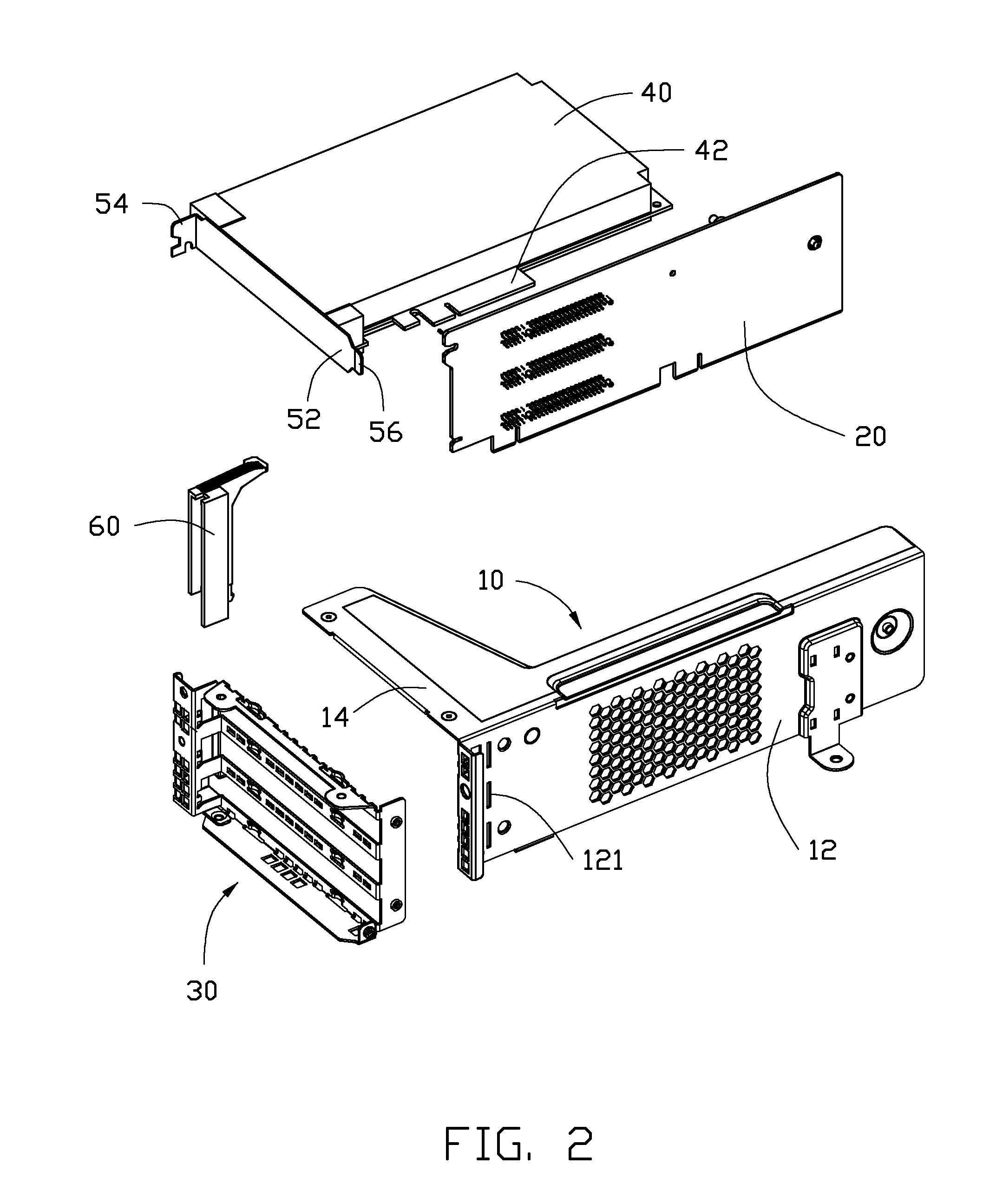
[0013]Referring to FIGS. 1 and 2, an embodiment of an expansion card mounting assembly includes a mounting bracket 10, a riser card 20, a mounting frame 30, an expansion card 40, a shield plate 50 attached to a rear side of the expansion card 40, and a latch member 60.

[0014]The mounting bracket 10 includes a side panel 12 and a top panel 14 perpendicularly connected to a top edge of the side panel 12. A plurality of receiving slots 121 and a pair of first securing holes 123 are defined in the side panel 12 of the mounting bracket 10. A limiting piece 125 extends from the side panel 12 of the mounting bracket 10. A gap 1251 is defined in the limit...


PUM


Abstract

A mounting assembly includes a mounting bracket, a riser card, a shield plate attached to an expansion card, a mounting frame, and a latch member. The riser card is attached to the mounting bracket and has at least one expansion card socket. The expansion card is received in the at least one expansion card socket. The mounting frame has at least one slot configured to fix the shield plate and an accommodating space beside the at least one slot. The latch member is mounted in the accommodating space and abuts the shield plate for preventing the expansion card from moving away from the at least one expansion card socket. The latch member is capable of being taken out from the accommodating space to release the shield plate, thereby allowing the expansion card to disengage from the at least one expansion card socket.

Description

BACKGROUND[0001]1. Technical Field[0002]The present disclosure relates to mounting assemblies, more particularly to an expansion card mounting assembly.[0003]2. Description of Related Art[0004]In some computer systems, riser cards are connected perpendicular to motherboards of the computer systems. Expansion card sockets are mounted on the riser cards receiving corresponding expansion cards parallel to the motherboards. This arrangement can save space in the computer systems. After the expansion cards are received in the expansion card socket, the expansion cards are further secured to the chassis of the computer systems by securing means. However, such securing means often utilize fasteners or fasteners to secure the expansion cards, complicating installation and removal of the expansion cards.[0005]Therefore, there is still room for improvement within the art.BRIEF DESCRIPTION OF THE DRAWINGS[0006]Many aspects of the embodiments can be better understood with references to the foll...

Claims


Application Information

Patent Timeline
IPC IPC(8): H05K7/14
CPCG06F1/186G06F1/185
Inventor CHIU, PO-WENLI, ZHAN-YANG
Owner HONG FU JIN PRECISION IND (SHENZHEN) CO LTD
Why Eureka
Try Eureka