
Apparatus and Method for Testing One-Time-Programmable Memory

a one-time-programmable and memory technology, applied in the field of one-time-programmable memory testing, can solve problems such as the breakdown of the entire system

Active Publication Date: 2012-01-26
ANALOG DEVICES INC
View PDF2 Cites 3 Cited by
  • Summary
  • Abstract
  • Description
  • Claims
  • Application Information

AI Technical Summary

Benefits of technology

The patent text describes a method for testing a one-time-programmable memory by limiting the current flow through the memory. This is done by imposing a high impedance between the voltage source and the memory. If the blow signal assertion circuitry is not defective, the fuse will not be blown. The current signal during testing is less than the threshold current for blowing the fuse. The technical effect of this method is to ensure safe and reliable testing of the one-time-programmable memory without causing damage to the fuse.

Problems solved by technology

The technical problem addressed in this patent text is the potential for a one-time-programmable memory to malfunction an entire system if its programming circuitry or memory is defective. This is because the memory is often programmed after it is integrated into a larger system, and testing of its function is not performed until it is within that system.

Method used


Image

  • Apparatus and Method for Testing One-Time-Programmable Memory
  • Apparatus and Method for Testing One-Time-Programmable Memory
  • Apparatus and Method for Testing One-Time-Programmable Memory

Examples


Embodiment Construction

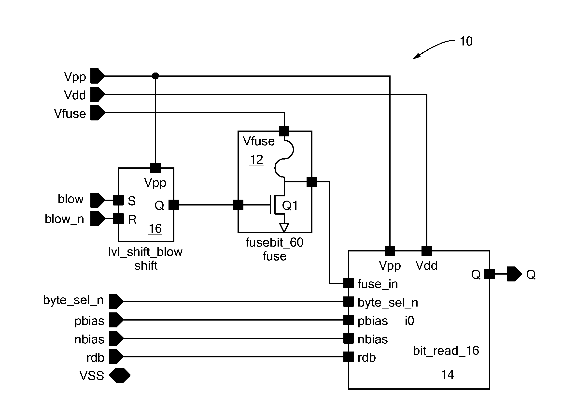
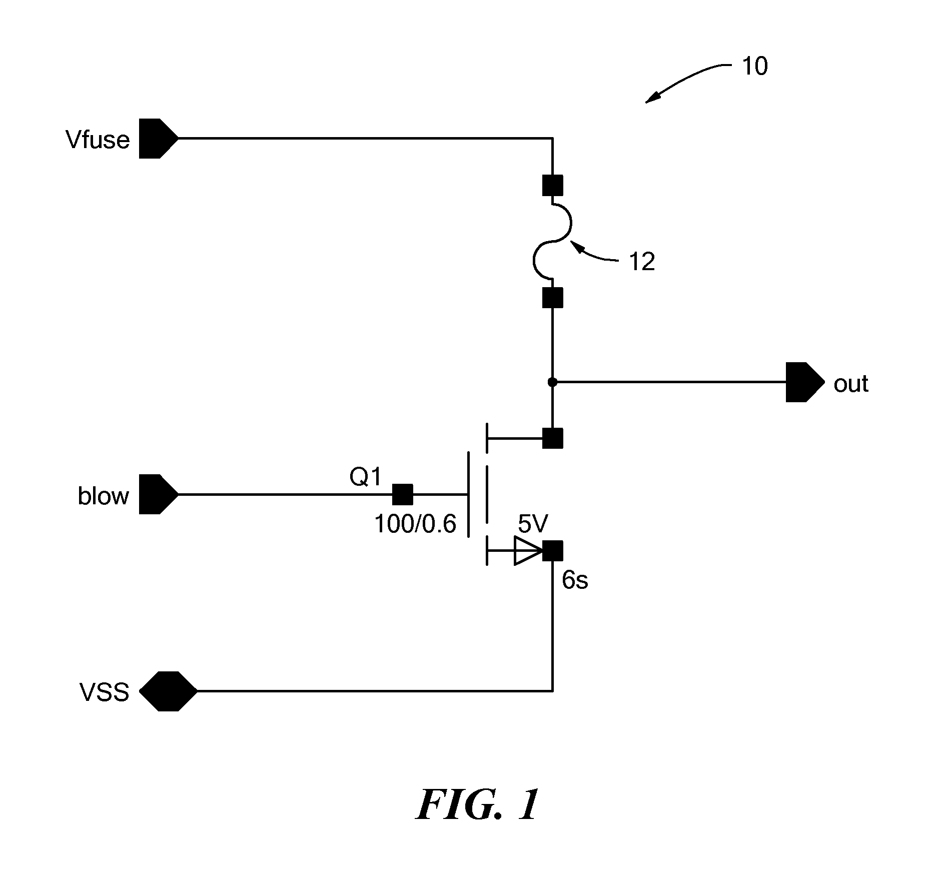
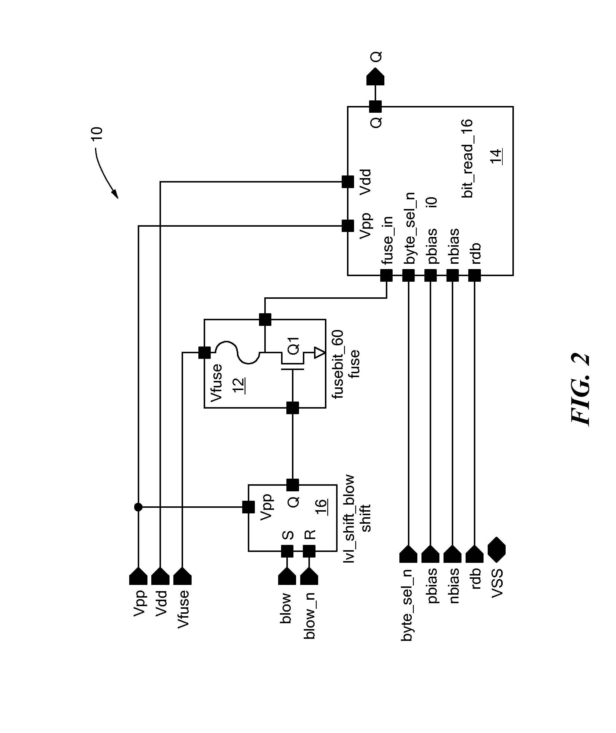
[0004]In accordance with one embodiment of the invention, an apparatus and method of testing one-time-programmable memory limits current flow through the one-time-programmable memory to a low amplitude signal, wherein the one-time-programmable memory has a fuse configured to blow upon receipt of a signal having a threshold amplitude. The low amplitude signal is less than the threshold amplitude. The method also uses blow circuitry to attempt to assert a blow signal to the fuse. When not defective, blow circuitry is configured to permit the low amplitude signal to flow through the fuse when the fuse is not blown and the blow signal is asserted. The fuse does not blow in response to flow of the low amplitude signal. The method then produces an output signal having a success value if the low amplitude signal flows through the fuse, and a failure value if the low amplitude signal does not flow through the fuse.

[0005]Limiting current flow through the one-time-programmable memory may invo...


PUM


Abstract

An apparatus and method of testing one-time-programmable memory limits current through a one-time-programmable memory to less than a threshold amplitude, where the memory has a fuse configured to blow upon receipt of a signal having the threshold amplitude. The method also uses blow signal assertion circuitry to attempt to assert a blow signal to the fuse. When not defective, blow signal assertion circuitry is configured to permit the low amplitude signal to flow through the fuse when the fuse is not blown and the blow signal is asserted. The method then produces an output signal having a success value if the limited current flows through the fuse, and a failure value if the current does not flow through the fuse.

Description


Claims


Application Information

Patent Timeline
Owner ANALOG DEVICES INC
Learn More