Optical fiber configurations for transmission of laser energy over great distances

a technology of optical fibers and lasers, applied in the field of optical fiber configurations, can solve the problems of fiber heating and ultimate failure, failure to deliver high-power laser energy over great distances, and failure to eliminate the phenomenon of stimulated raman scattering (“srs”)

Active Publication Date: 2012-01-26
FORO ENERGY
View PDF11 Cites 91 Cited by
  • Summary
  • Abstract
  • Description
  • Claims
  • Application Information

AI Technical Summary

Benefits of technology

[0012]It is desirable to have an optical fiber configuration that provides for the delivery of laser energy and in particular high power laser energy over great distances and without substantial power loss, in particular losses from bending. The present invention, among other things, solves these needs by providing the articles of manufacture, devices and processes taught herein.

Problems solved by technology

Although Muto states that 4 kW of power were delivered down a 1 km fiber, when 5 kW of laser power was put into the fiber, Muto fails to eliminate the stimulated Raman scattering (“SRS”) phenomena.
Further, SBS, SRS, as well as the other deleterious nonlinear effects, in addition to limiting the amount of power that can be transmitted out of the fiber, can result in fiber heating and ultimate failure.
The physical phenomenon which restricts the transmitted power is SRS.” Thus, Muto, as did others before him, failed to deliver high power laser energy over great distances.
Further, Muto does not disclose, discuss or address the placing of its optical fiber in any protective tubing or material, the coiling and uncoiling of its fiber or the strengthening of its fiber for use in a particular application.
In particular, Muto does not address the bending losses associated with such configurations and, in particular, the bending losses that are associated with strengthened configurations.

Method used


Image

  • Optical fiber configurations for transmission of laser energy over great distances
  • Optical fiber configurations for transmission of laser energy over great distances
  • Optical fiber configurations for transmission of laser energy over great distances

Examples


example 1

[0081]Inner radius of the outer protective member, ROPM=1.5 mm (millimeters).

[0082]Outer radius of the fiber (including coating) RF[L]=400 μm (microns).

[0083]Temperature change that the configuration must sustain in the intend use, ΔT [T]=100° C.

[0084]Mechanical strain that configuration must sustain in the intend use, ε=0.0005

[0085]Coefficient of thermal expansion of the fiber, CTEF=0.55*10−6 (1 / C).

[0086]Coefficient of thermal expansion of the outer protective member, CTEOPM=15*10−6 (1 / C).

[0087]Length of outer protective member at ambient temperature and no mechanical strain, LOPM=2 km.

[0088]Minimum bend radius of fiber, RFmin=10 cm.

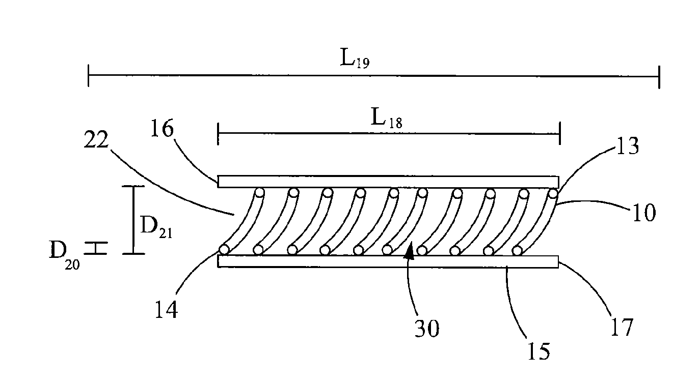
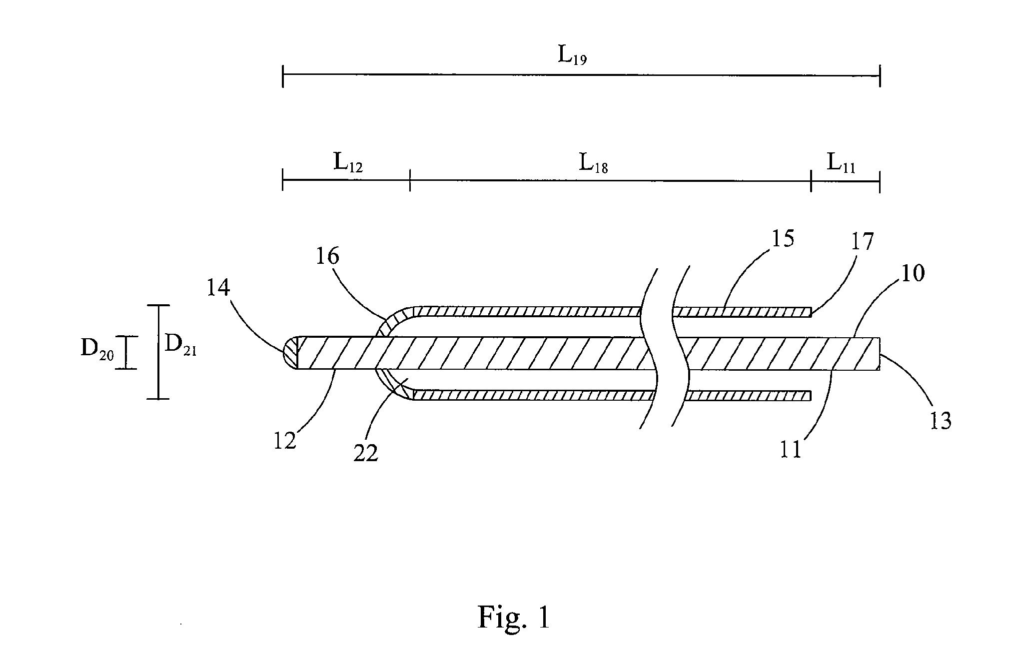
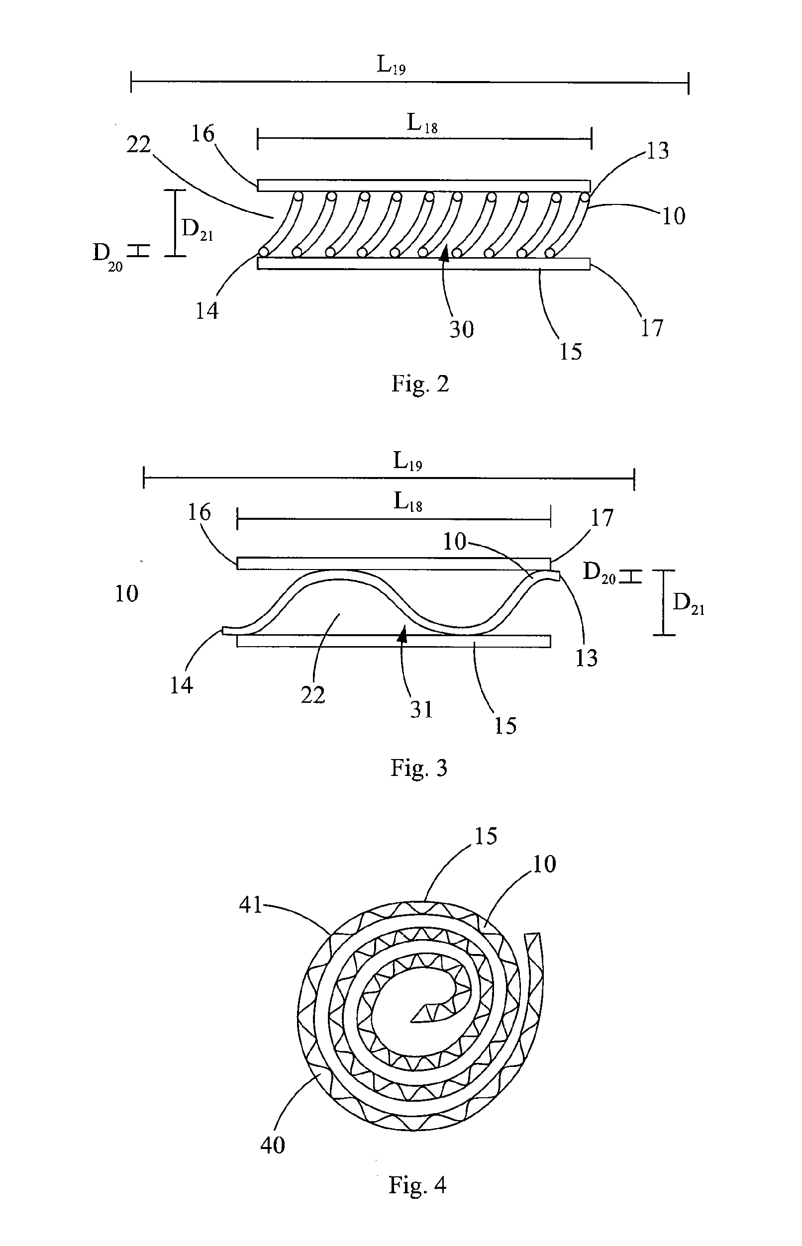
[0089]Inner radius of a coil (for example of the type shown in FIG. 4) of the configuration, Rcoil=1.5 m.

[0090]Wherein, the AFL[L] for a helical non-following path (for example of the type shown in FIG. 2) is from about 3.89 to about 10.4 m; the AFL[%] for a helical non-following path is from about 0.195% to about 0.517%. Wherein, the AFL[L] for a sinus...

example 2

[0091]Inner radius of the outer protective member, ROPM=3 mm (millimeters).

[0092]Outer radius of the fiber (including coating) RF [L]=250 μm.

[0093]Temperature change that the configuration must sustain in the intend use, ΔT [T]=10° C.

[0094]Mechanical strain that configuration must sustain in the intend use, ε=0.0001.

[0095]Coefficient of thermal expansion of the fiber, CTEF=0.55*10−6 (1 / C).

[0096]Coefficient of thermal expansion of the outer protective member, CTEOPM=15*10−6 (1 / C).

[0097]Length of outer protective member at ambient temperature and no mechanical strain, LOPM=1 km.

[0098]Minimum bend radius of fiber, RFmin=20 cm.

[0099]Inner radius of a coil (for example of the type shown in FIG. 4) of the configuration, Rcoil=1 m.

[0100]Wherein, the AFL[L] for a helical non-following path (for example of the type shown in FIG. 2) is from about 0.245 to about 5.55 m; the AFL[%] for a helical non-following path is from about 0.0245% to about 0.555%. Wherein, the AFL[L] for a sinusoidal non-f...

example 3

[0101]Inner radius of the outer protective member, ROPM=1.6 mm (millimeters).

[0102]Outer radius of the fiber (including coating) RF [L]=100 μm.

[0103]Temperature change that the configuration must sustain in the intend use, ΔT [T]=50° C.

[0104]Mechanical strain that configuration must sustain in the intend use, ε=0.0002.

[0105]Coefficient of thermal expansion of the fiber, CTEF=0.55*10−6 (1 / C).

[0106]Coefficient of thermal expansion of the outer protective member, CTEOPM=26*10−6 (1 / C).

[0107]Length of outer protective member at ambient temperature and no mechanical strain, LOPM=3 km.

[0108]Minimum bend radius of fiber, RFmin=10 cm.

[0109]Inner radius of a coil of the configuration, Rcoil=50 cm.

[0110]Wherein, the AFL[L] for a helical non-following path (for example of the type in FIG. 2) is from about 4.42 to about 18.2 m; the AFL[%] for a helical non-following path is from about 0.147% to about 0.61%. Wherein, the AFL[L] for a sinusoidal non-following path (for example of the type shown in...


PUM


Abstract

There are provided optical fiber configurations that provide for the delivery of laser energy, and in particular, the transmission and delivery of high power laser energy over great distances. These configurations further are hardened to protect the optical fibers from the stresses and conditions of an intended application. The configurations provide means for determining the additional fiber length (AFL) need to obtain the benefits of such additional fiber, while avoiding bending losses.

Description

[0001]This invention was made with Government support under Award DE-AR0000044 awarded by the Office of ARPA-E U.S. Department of Energy. The Government has certain rights in this invention.BACKGROUND OF THE INVENTION[0002]1. Field of the Invention[0003]The present invention relates to configurations of optical fibers that provide the ability to assemble, spool and unspool, deploy or use such configurations, while maintaining the fiber's ability to transmit laser energy over distances, and in particular, over great distance and at high powers. The present invention further relates to configurations that are strengthened to withstand harsh environments, such as the environments found in a borehole, a nuclear plant, or under the sea. In particular, the present invention relates to unique and novel configurations utilizing additional fiber length to minimize bending losses while providing benefits for selected predetermined applications.[0004]As used herein, unless specified otherwise ...

Claims


Application Information

Patent Timeline
Patent Type & Authority Applications(United States)
IPC IPC(8): G02B6/44B23P11/00
CPCG02B6/4413G02B6/443G02B6/4415Y10T29/49826G02B6/4402G02B6/4458
Inventor RINZLER, CHARLES C.ZEDIKER, MARK S.
Owner FORO ENERGY
Why Eureka
Try Eureka