Rotary spindle head for machine tool

Inactive Publication Date: 2012-01-26
IND TECH RES INST
View PDF8 Cites 16 Cited by
  • Summary
  • Abstract
  • Description
  • Claims
  • Application Information

AI Technical Summary

Benefits of technology

[0013]The primary object of the present disclosure is to provide a high-speed, high-torque rotary spindle head for machine tools that is capable of overcoming the aforesaid shortcomings.
[0014]Another object of the present disclosure is to provide a rotary spindle head of good dynamic balance.
[0017]Moreover, since the torque motor and the planetary-gear speed reducer are coaxially disposed that allows the spindle head to have a compact and symmetric configuration, not only the torque density is increased and the dynamic load is dispersed, but also a good dynamic balance can be obtained during the operation of the rotary spindle unit.

Problems solved by technology

However, the foresaid design using serve motors coupled to a speed reduction mechanism of high reduction ratio is short in that: (a) the mechanical transmission of high reduction ratio can cause considerable loss in mechanical efficiency in comparison to other transmission means; (b) the mechanical transmission of high reduction ratio will greatly reduce the rotation speed of the spindle head so that it can not be used for high speed machining; and (c) the mechanical transmission of high reduction ratio usually is designed with larger volume that the design degree-of-freedom of the rotary spindle head can be adversely affected.
Nevertheless, in addition to the cost increasing from the use of two torque motors, in a design point of view, when larger torque motors with larger torque outputs are chosen for conforming to the operation requirement of its spindle head, the overall volume as well as cost will increase with the increasing of its torque motor size and thus the design flexibility is compromised.
However, in U.S. Pat. No. 7,470,095, not only the torque motors are not disposed coaxially to the rotation axis of the spindle head, but also the selection of the torque motors along with the transmission mechanism that are capable of being used in this disclosure are restricted by the limited space available, so that the output torque of the spindle head resulting from the aforesaid disclosure is only ideal for light and medium machining applications.
Moreover, since its input shaft and output shaft are not coaxially disposed, the dynamic balance of this disclosure is not satisfactory that requires to be improved.

Method used


Image

  • Rotary spindle head for machine tool
  • Rotary spindle head for machine tool
  • Rotary spindle head for machine tool

Examples


Embodiment Construction

[0035]For your esteemed members of reviewing committee to further understand and recognize the fulfilled functions and structural characteristics of the disclosure, several exemplary embodiments cooperating with detailed description are presented as the follows.

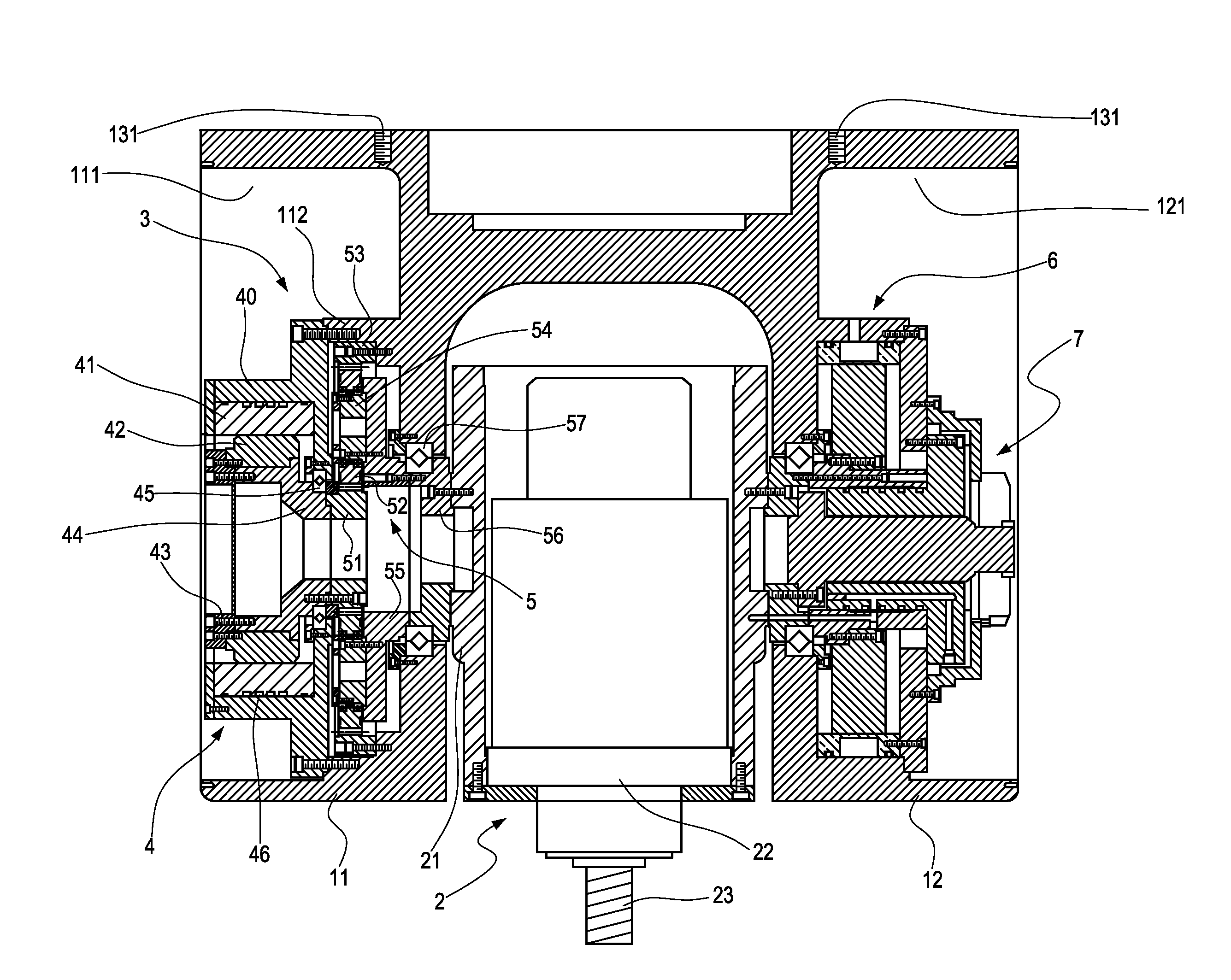
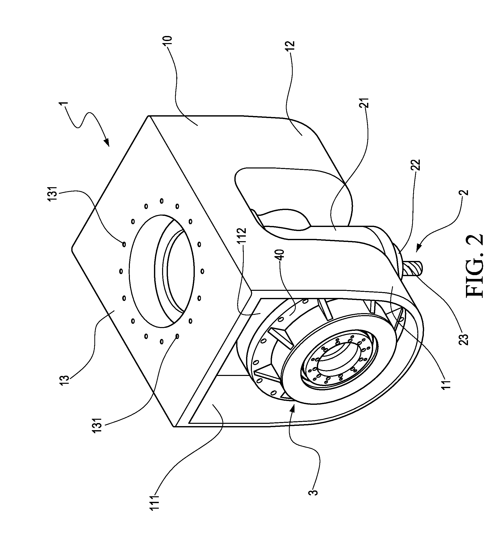
[0036]Please refer to FIG. 2 to FIG. 6, in which FIG. 2 is a three-dimensional view of a rotary spindle head according to an embodiment of the present disclosure; FIG. 3 is another three-dimensional view of the rotary spindle head of FIG. 2, but from a viewing angle different from that of FIG. 2; FIG. 4 is a cross sectional view of a rotary spindle head according to an embodiment of the present disclosure; FIG. 5 is a cross sectional view of a planetary-gear speed reducer used in the present disclosure; and FIG. 6 is a side view of a planetary-gear speed reducer used in the present disclosure.

[0037]As shown in FIG. 2, a rotary spindle head of the present disclosure, being adapted for a machine tool, is primarily composed of: ...


PUM

PropertyMeasurementUnit
Circumferenceaaaaaaaaaa

Abstract

A rotary spindle head for a machine tool, comprises a rotary spindle unit, a fork-shaped spindle base, and a driving unit, wherein the fork-shaped spindle base is disposed to the machine tool and is rotatably connecting to the rotary spindle unit, while the driving unit, having a torque motor and a planetary-gear speed reducer coaxially coupled to the torque motor, is coupled to the fork-shaped spindle base. The planetary-gear speed reducer is coupled to the rotary spindle unit for driving the rotary spindle unit to rotate within the fork-shaped spindle base. Since the planetary-gear speed reducer has lower speed reduction ratio and has a speed reducing design with the coaxial arrangement of the input / output shafts, it is capable of magnifying the torque of the torque motor for retaining a higher rotation speed so that the rotary spindle head can be utilized for high-speed light-machining and high-torque heavy-machining.

Description

CROSS-REFERENCE TO RELATED APPLICATIONS[0001]This non-provisional application claims priority under 35 U.S.C. §119(a) on Patent Application No(s). 099123784 filed in Taiwan, R.O.C. on Jul. 20, 2010, the entire contents of which are hereby incorporated by reference.TECHNICAL FIELD[0002]The present disclosure relates to a spindle head for multi-axis machine tools, and more particularly, to a high-speed, high-torque rotary spindle head for machine tools.TECHNICAL BACKGROUND[0003]With rapid advance of alternative energy industry, such as wind power generation, the demand for large-scale, multi-axis / multi-process machine tools is increasing therewith. Consequently, the demand for rotary spindle heads used in those machine tools that are capable of withstanding high torque and high rotation speed are increasing as well.[0004]Please refer to FIG. 1, which shows a conventional large-scale multi-axis machine tool. As shown in FIG. 1, a working bench 82 that is mounted on a first rail set 81 ...

Claims


Application Information

Patent Timeline
IPC IPC(8): B23C1/12
CPCB23Q1/5406B23Q5/12Y10T409/307672B23Q2220/006B23Q2210/004
Inventor OU, FENG-MINGHSING, YU-HSIHSIAO, HSI-HUNGLIN, CHING-YUAN
Owner IND TECH RES INST
Why Eureka
Try Eureka