Celestial weapons orientation measuring system

a technology of orientation measuring and a measuring system, applied in weapons, training adaptation, instruments, etc., can solve problems such as inability to operate and degrade performance, and achieve the effects of accurate measurement of rifle pitch and roll, reduced bias errors of gyros, and improved accuracy

Active Publication Date: 2012-01-26
TREX ENTERPRISES CORP
View PDF15 Cites 28 Cited by
  • Summary
  • Abstract
  • Description
  • Claims
  • Application Information

AI Technical Summary

Benefits of technology

[0033]The inertial navigation sensor integrates three inertial sensor technologies: gyroscopes, accelerometers, and magnetometers. Accelerometers and magnetometers are used to measure the Earth references of gravity and magnetic field. By utilizing three orthogonally mounted accelerometers, the sensor is able to accurately measure the pitch and roll of the rifle with accuracy better than 1.7 mils. The heading is determined from the magnetic field data. Three orthogonally mounted gyroscopes provide information on the dynamic motion of the hand-held weaponry. The system includes an adaptive Kalman filter algorithm reduces the bias errors of the gyros.

Problems solved by technology

Embodiments that rely solely on clear skies have limitations:a) They cannot operate in the presence of heavy clouds, fog, and smoke,b) Highly dynamic conditions can degrade performance andc) These embodiments cannot operate in indoor conditions.

Method used


Image

  • Celestial weapons orientation measuring system
  • Celestial weapons orientation measuring system
  • Celestial weapons orientation measuring system

Examples


Embodiment Construction

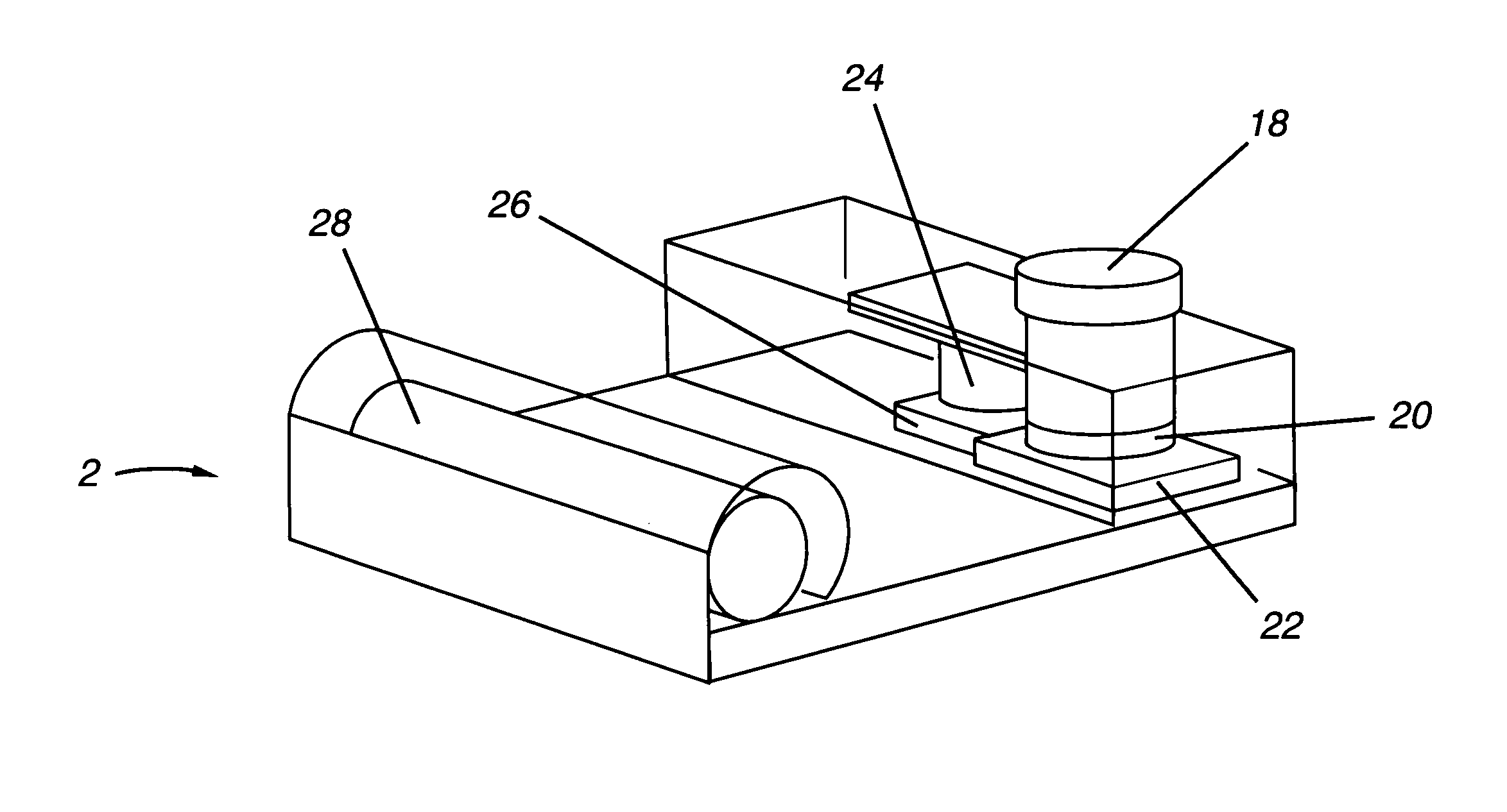
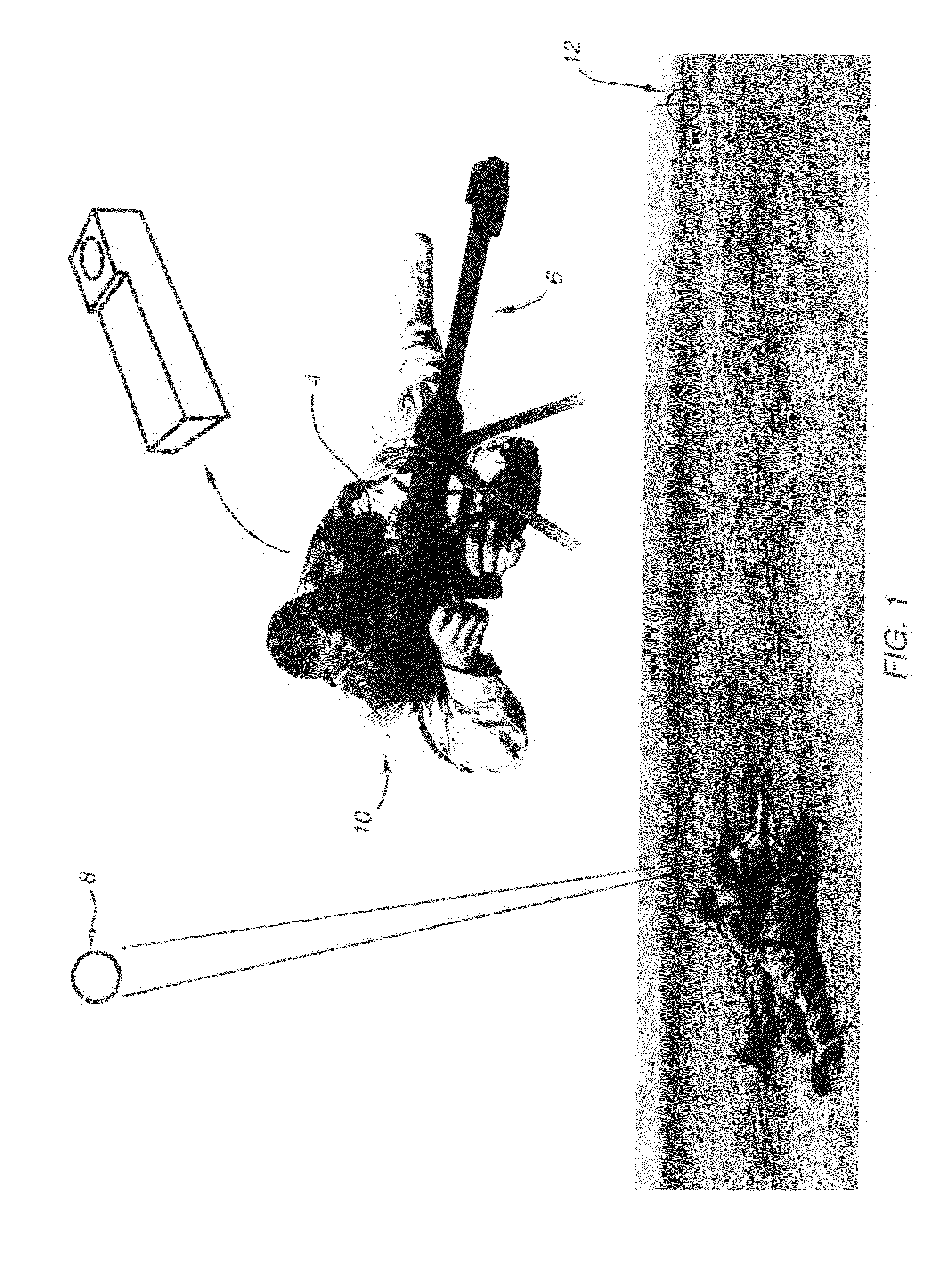
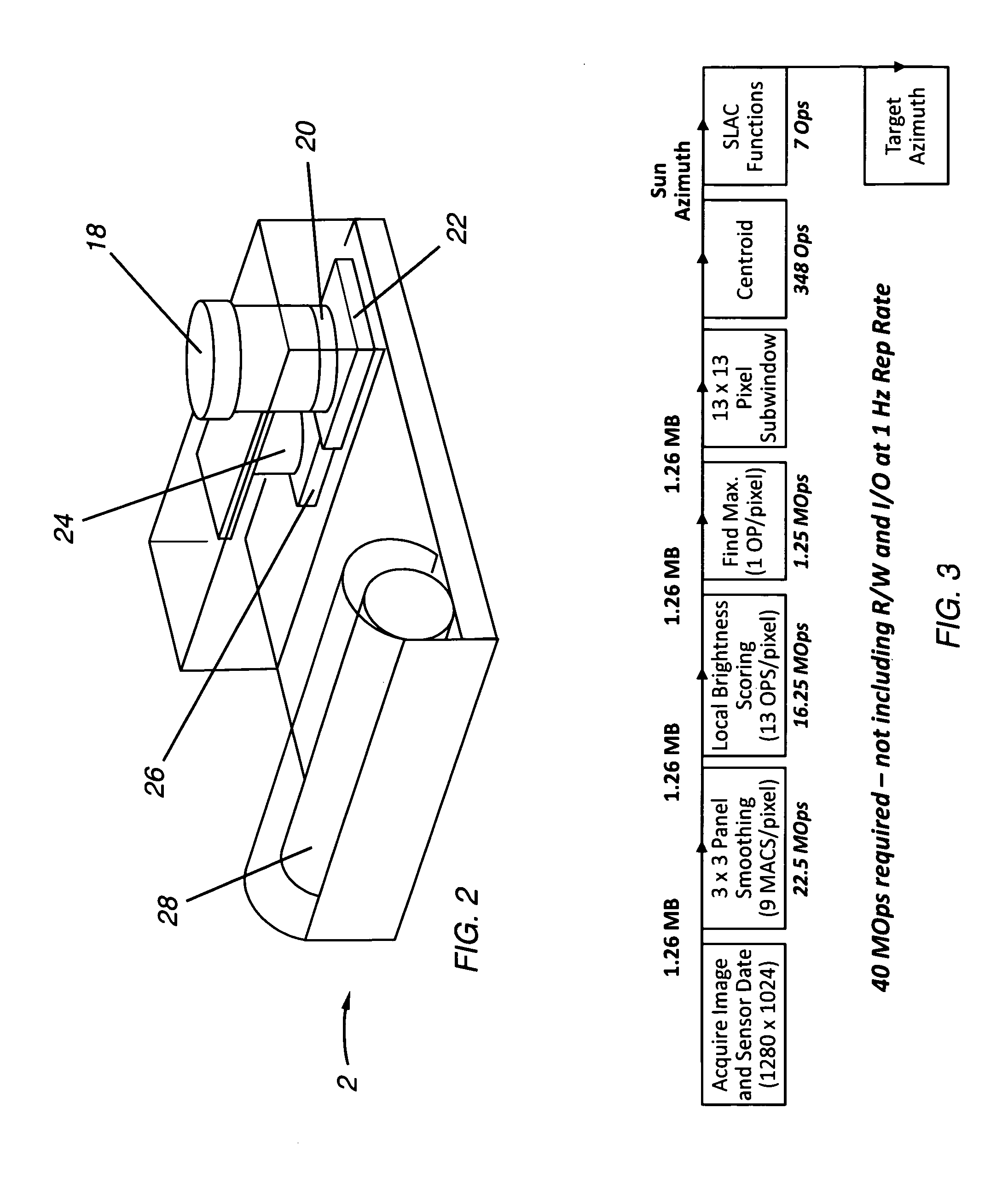
[0042]Preferred embodiments of the present invention can be described by reference to the drawings. A preferred embodiment is shown in FIG. 1. A preferred module 2 of the present invention is mounted on a telescopic sight 4 which is in turn mounted on a M82 0.50 caliber sniper rifle 6. The pointing direction of the rifle is determined by a processor (not shown) contained in module 2 based inputs from a MEMS inclinometer (not shown) contained in module 2 and on the position of the sun 8 and the known date and time reference to a star catalog of the type discussed in the background section. The pointing direction of the rifle 6 when the rifle trigger is pulled by soldier 10 is transmitted via a radio transmitter to a control facility housing a control computer processor. A GPS unit on the target continuously transmits the latitude, longitude and elevation of the target 12 (which may be a pretend enemy soldier in motion) to the control facility. The computer processor utilizing special...


PUM


Abstract

A celestial weapons orientation measuring system. The system includes a miniature celestial direction detection device. The device includes an inclinometer, a camera for imaging at least one celestial object and a processor programmed with a celestial catalog providing known positions at specific times of at least one celestial object and algorithms for automatically calculating target direction information based on the inclination of the system as measured by the inclinometer and the known positions of the celestial object as provided by the celestial catalog and as imaged by the camera. Similar to the training technique discussed in the background section, the pretend enemy wears a GPS detector and transmitter, and a computer system is preferably provided which determines when a trigger-pull results in a “casualty”. Preferred embodiments also include an inertial navigation sensor including a magnetic compass and a memory-based optical navigation system that permits continued operation on cloudy days and even in certain in-door environments.

Description

CROSS REFERENCE TO RELATED APPLICATIONS[0001]This application is a continuation in part of patent application Ser. No. 11 / 604,133, Celestial Compass, filed Nov. 24, 2006, Ser. No. 12 / 283,785, Portable Celestial Compass filed Sep. 15, 2008, Ser. No. 12 / 319,651, Angles Only Navigation System filed Jan. 8, 2008 and Ser. No. 12 / 583,776 Miniature Celestial Direction Detector filed Aug. 25, 2009, each of which are incorporated herein by reference. This application also claims the benefit of Provisional Patent Application Ser. No. 61 / 194,308 filed Sep. 26, 2008.FEDERAL SUPPORTED RESEARCH[0002]The present invention was made in the course of work under contract number N00178-08-C-0019 with the United States Navy and the United States Government had rights in the invention.FIELD OF INVENTION[0003]The present invention relates to direction detection systems, especially to such systems designed for use in determination of precise locations of targets.BACKGROUND OF THE INVENTIONSky Charts[0004]T...

Claims


Application Information

Patent Timeline
Patent Type & Authority Applications(United States)
IPC IPC(8): F41G3/26
CPCG09B27/00F41G3/26
Inventor BELENKII, MIKHAILBRUNS, DONALDBRINKLEY, TIMOTHY
Owner TREX ENTERPRISES CORP
Why Eureka
Try Eureka