Bias error correction in an optical coherent transponder

a technology of optical coherent transponders and bias errors, applied in electromagnetic transceivers, transmission monitoring/testing/fault measurement systems, wavelength-division multiplex systems, etc., can solve problems such as high equipment costs, bias errors in optical coherent transponders, and inability to accurately measure q non-orthogonality, so as to reduce bias errors

Active Publication Date: 2017-12-05
FUJITSU LTD
View PDF6 Cites 0 Cited by
  • Summary
  • Abstract
  • Description
  • Claims
  • Application Information

AI Technical Summary

Benefits of technology

[0007]In any of the disclosed embodiments, the method may include changing, in response to detecting the bias error in the modulator, a bias voltage of the modulator. Changing the bias voltage of the modulator reduces the bias error in the optical coherent transponder.
[0016]In any of the disclosed embodiments, the bias error corrector may further include circuitry to change a bias voltage of the modulator in response to detection of the bias error in the modulator, and the change may effect a reduction of the bias error in the optical coherent transponder.

Problems solved by technology

Bias errors in the modulators in the optical coherent transponders can contribute to non-orthogonality.
Existing skew measurement methods and measurements of I / Q non-orthogonality are not very accurate for complex modulation formats (such as 16-QAM), and the equipment needed to perform the measurements can be very expensive.
For example, some existing skew measurement techniques rely on the use of expensive Optical Modulation Analyzers (OMAs).

Method used


Image

  • Bias error correction in an optical coherent transponder
  • Bias error correction in an optical coherent transponder
  • Bias error correction in an optical coherent transponder

Examples


Embodiment Construction

)

[0036]In the following description, details are set forth by way of example to facilitate discussion of the disclosed subject matter. It should be apparent to a person of ordinary skill in the field, however, that the disclosed embodiments are exemplary and not exhaustive of all possible embodiments.

[0037]Throughout this disclosure, a hyphenated form of a reference numeral refers to a specific instance of an element and the un-hyphenated form of the reference numeral refers to the element generically or collectively. Thus, as an example (not shown in the drawings), device “12-1” refers to an instance of a device class, which may be referred to collectively as devices “12” and any one of which may be referred to generically as a device “12”. In the figures and the description, like numerals are intended to represent like elements.

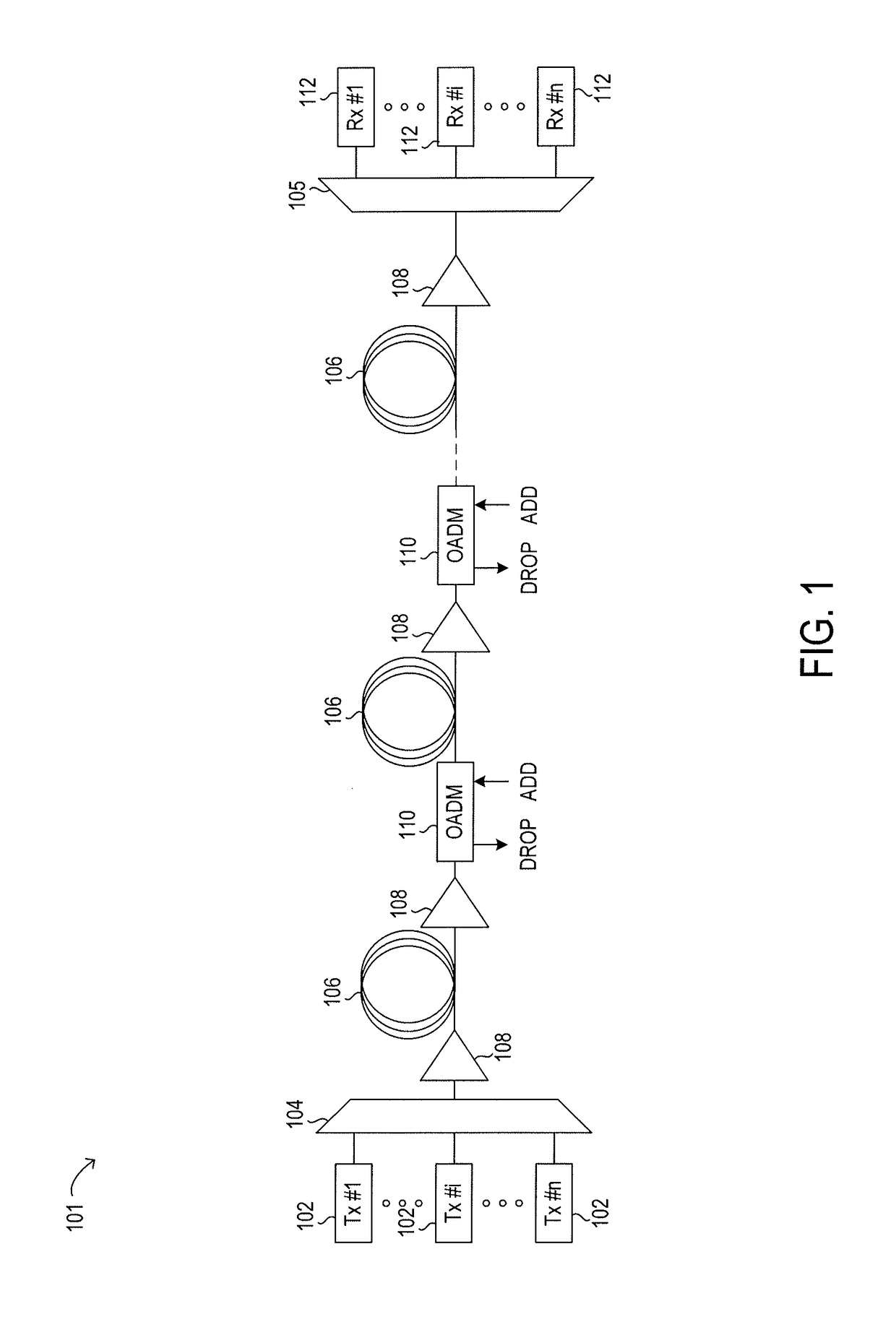
[0038]Referring now to the drawings, FIG. 1 illustrates an example embodiment of optical network 101, which may represent an optical communication system. ...


PUM


Abstract

Systems and methods for detecting and correcting bias errors in optical coherent transponders are disclosed. An “outer” modulator in a transponder may, when properly biased, produce a phase offset of π / 2 radians between in-phase and quadrature components of the optical signals transmitted in optical modulation formats by the transponder. The method may include providing input to a transponder to produce a periodic (and generally sinusoidal) output signal, measuring (using an optical power meter) the optical power of positive and negative harmonics of the signal while varying the amount of skew introduced by a de-skewing filter in the transponder, and determining that a curve representing the measurements performed on the positive harmonics and a curve representing the measurements performed on the negative harmonics are not orthogonal. The method may include adjusting the bias voltage of the modulator to make the two curves orthogonal, thus eliminating the bias error.

Description

BACKGROUNDField of the Disclosure[0001]The present disclosure relates generally to optical communication networks and, more particularly, to systems and methods for detecting and correcting bias errors in optical coherent transponders.Description of the Related Art[0002]Telecommunication, cable television and data communication systems use optical networks to rapidly convey large amounts of information between remote points. In an optical network, information is conveyed in the form of optical signals through optical fibers. Optical fibers may comprise thin strands of glass capable of communicating the signals over long distances. Optical networks often employ modulation schemes to convey information in the optical signals over the optical fibers. Such modulation schemes may include phase-shift keying (PSK), frequency-shift keying (FSK), amplitude-shift keying (ASK), pulse-amplitude modulation (PAM), and quadrature amplitude modulation (QAM).[0003]Optical networks may also include v...

Claims


Application Information

Patent Timeline
Patent Type & Authority Patents(United States)
IPC IPC(8): H04B10/07H04J14/02H04B10/40H04B10/079
CPCH04B10/07955H04J14/02H04B10/40H04B10/5053H04B10/50575
Inventor BRAVI, EMILIOLIANG, QIAN
Owner FUJITSU LTD
Why Eureka
Try Eureka