
Power Flow Simulation System, Method and Device

a technology of power flow and simulation system, applied in non-electric variable control, process and machine control, instruments, etc., can solve the problems of large power distribution system, complex geometries, and difficulty in creating effective power distribution modeling solutions which opera

Inactive Publication Date: 2012-01-26
S&C ELECTRIC
View PDF6 Cites 225 Cited by
  • Summary
  • Abstract
  • Description
  • Claims
  • Application Information

AI Technical Summary

Problems solved by technology

However, power distribution systems are very large and can have very complex geometries.
As a result, there have been challenges in creating effective power distribution modeling solutions which operate in real time.
Further, as the demand for power increases, the size of power distribution systems increases, and the power grid becomes more complex, there is a need to better manage and control the flow of power.

Method used


Image

  • Power Flow Simulation System, Method and Device
  • Power Flow Simulation System, Method and Device
  • Power Flow Simulation System, Method and Device

Examples


Embodiment Construction

[0016]In the following description, for purposes of explanation and not limitation, specific details are set forth, such as particular networks, communication systems, computers, terminals, devices, components, techniques, data and network protocols, software products and systems, operating systems, development interfaces, hardware, etc. in order to provide a thorough understanding of the present invention.

[0017]However, it will be apparent to one skilled in the art that the present invention may be practiced in other embodiments that depart from these specific details. Detailed descriptions of well-known networks, communication systems, computers, terminals, devices, components, techniques, data and network protocols, software products and systems, operating systems, development interfaces, and hardware are omitted so as not to obscure the description of the present invention.

[0018]Some embodiments of the present invention provide power flow analysis software applications that oper...


PUM


Abstract

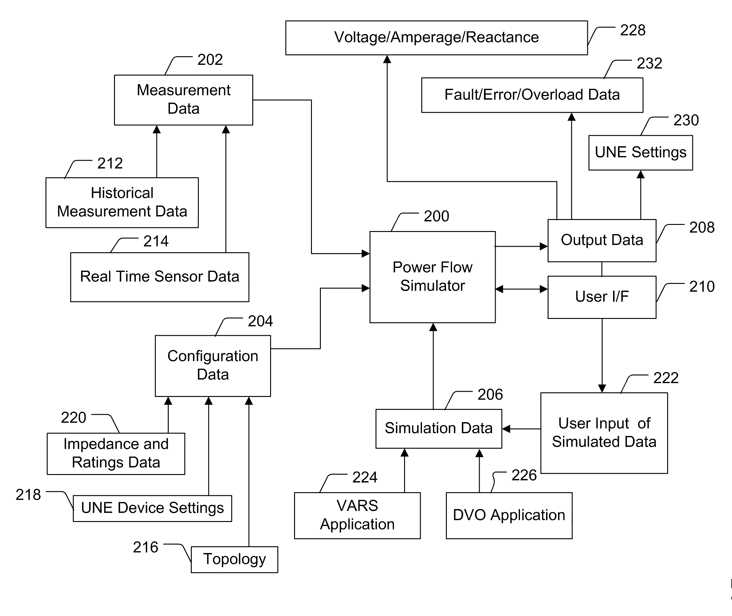
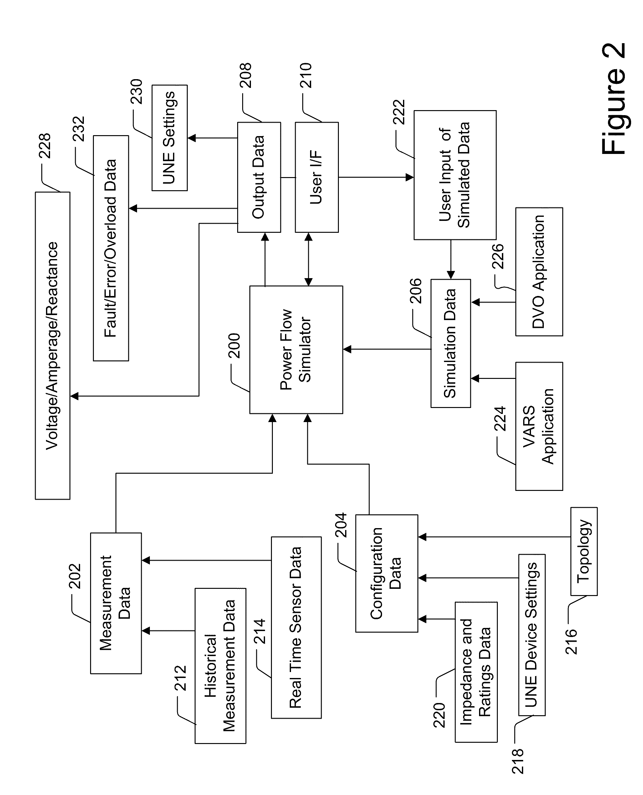
Embodiments of the present invention provide power flow analysis and may process electrical power distribution system data in real time to calculate load, current, voltage, losses, fault current and other data. The power flow analysis system may include a detailed data model of the electrical power distribution system, and may accept a variety of real time measurement inputs to support its modeling calculations. The power flow analysis system may calculate data of each of the three distribution system power phases independently and include a distribution state estimation module which allows it to incorporate a variety of real time measurements with varying degrees of accuracy, reliability and latency.

Description

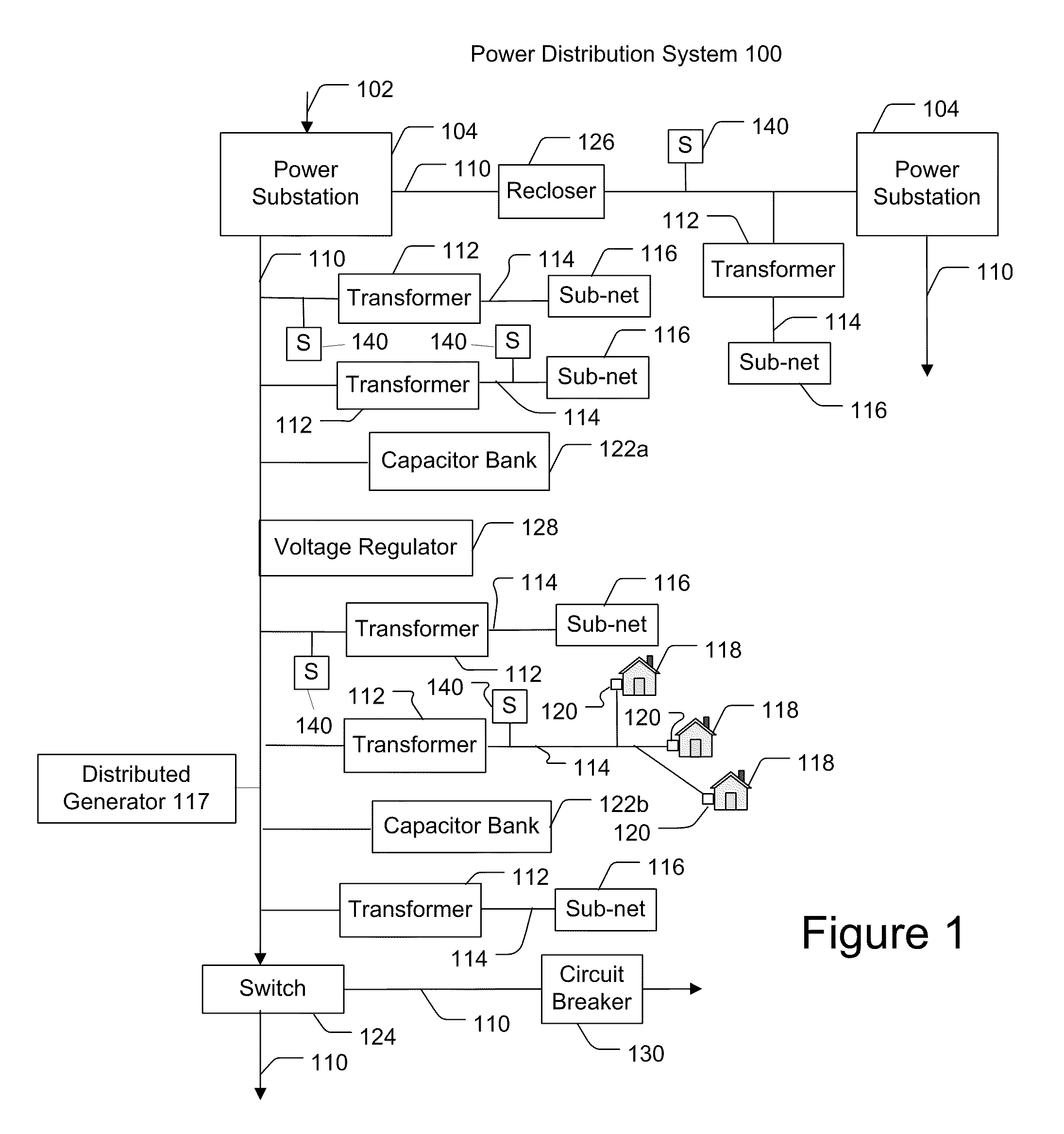
CROSS REFERENCE TO RELATED APPLICATIONS[0001]This application claims priority to U.S. Provisional Application No. 61 / 294,921, filed Jan. 14, 2010 and to U.S. Provisional Application No. 61 / 295,887, filed Jan. 18, 2010, which are both incorporated herein by reference in their entirety for all purposes.FIELD OF THE INVENTION[0002]The present invention generally relates to systems, methods and devices for simulating power flow, and more particularly for monitoring, modeling and controlling power flow in a power distribution network.BACKGROUND OF THE INVENTION[0003]The power system infrastructure includes power lines, transformers and other devices for power generation, power transmission, and power distribution. A power source generates power, which is transmitted along high voltage (HV) power lines for long distances. Typical voltages found on HV transmission lines range from 69 kilovolts (kV) to in excess of 800 kV. The power signals are stepped down to medium voltage (MV) power sign...

Claims


Application Information

Patent Timeline
IPC IPC(8): G06F1/28G06G7/63
CPCG05B17/02H02J3/00Y02E60/76Y04S40/22H02J2003/007H02J2203/20Y02E60/00Y04S40/20
Inventor DEAVER, SR., BRIAN J.PARIKH, PARAG A.
Owner S&C ELECTRIC
Learn More