Unitary breechblock assembly

a breechblock and assembly technology, applied in the field of single-shot break action firearms, can solve the problems of affecting the performance of cartridges, high cost, and breechblock portion of the receiver can become worn by the pivoting motion of the barrel, and achieves the effects of low cost, low cost, and minimal manufacturing cos

Inactive Publication Date: 2012-02-02
SMITH & WESSON
View PDF1 Cites 15 Cited by
  • Summary
  • Abstract
  • Description
  • Claims
  • Application Information

AI Technical Summary

Benefits of technology

[0008]According to the present invention, a firearm receiver is die cast at low cost and is adapted to receive a sl...

Problems solved by technology

The use of high quality materials and time-intensive manufacturing processes results in high costs.
One potential problem with economical firearms is that the breechblock portion of the receiver can become worn by pivo...

Method used


Image

  • Unitary breechblock assembly
  • Unitary breechblock assembly
  • Unitary breechblock assembly

Examples


Embodiment Construction

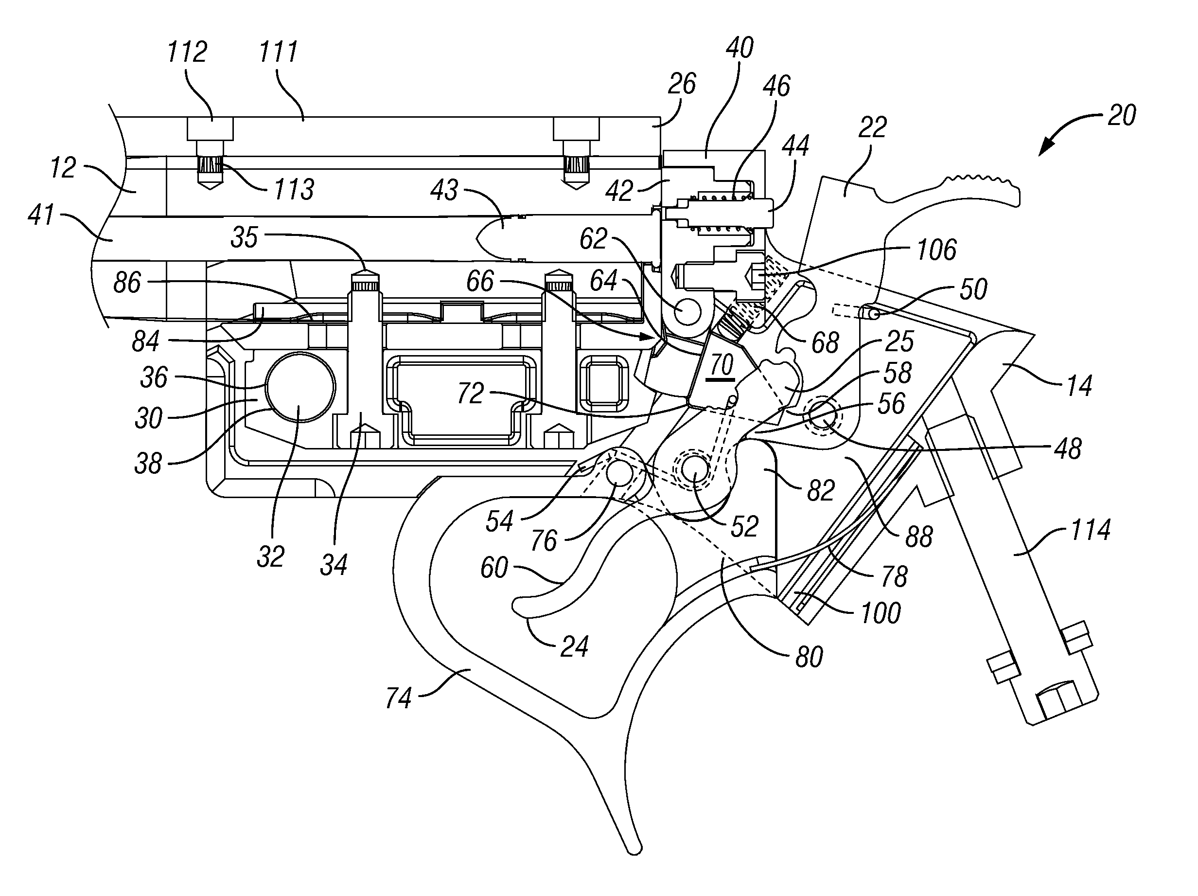
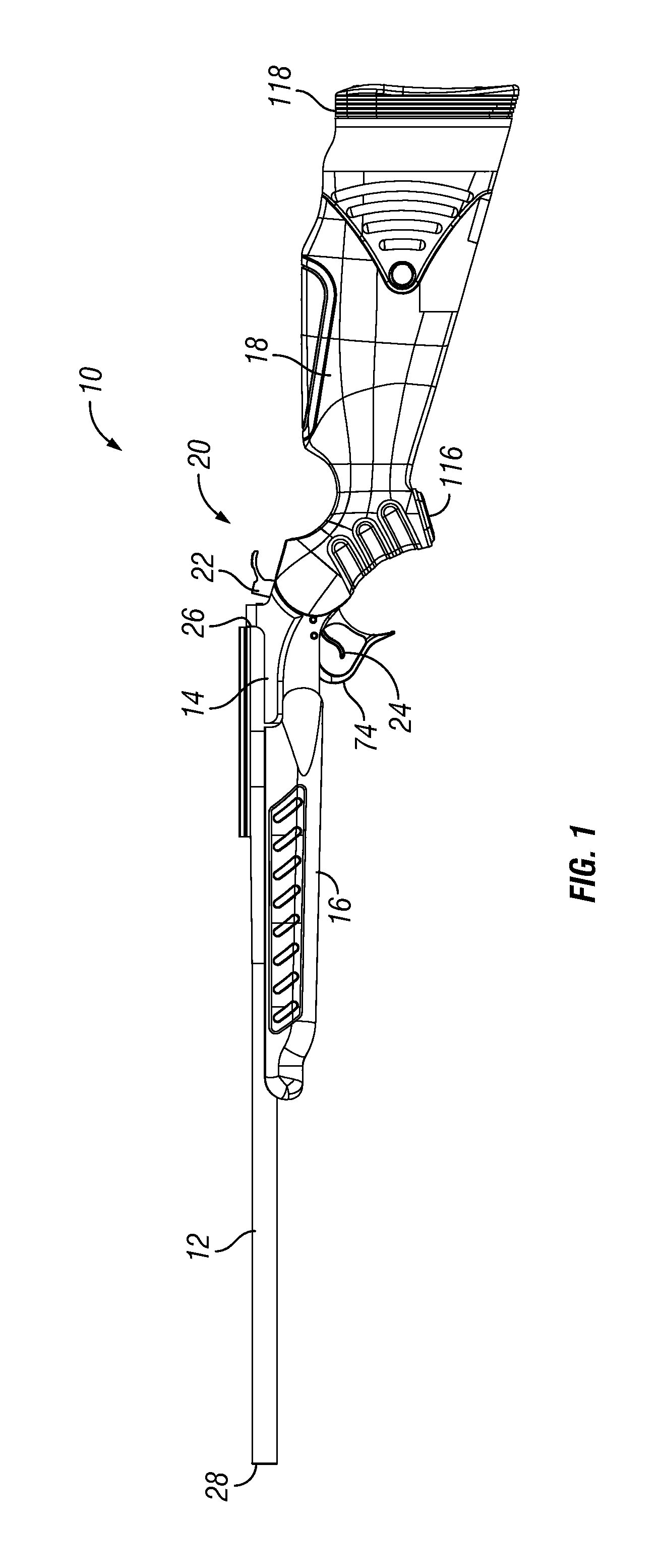
[0022]Referring to FIG. 1, a break action rifle 10 includes a barrel 12, which is pivotally mounted to a receiver 14 that supports a fore end 16 and a stock 18. The receiver also houses a firing mechanism 20, of which a hammer 22 and a trigger 24 are shown in FIG. 1, and a catch mechanism 66 (shown in FIG. 2). The barrel 12 has a breech end 26 and a muzzle end 28.

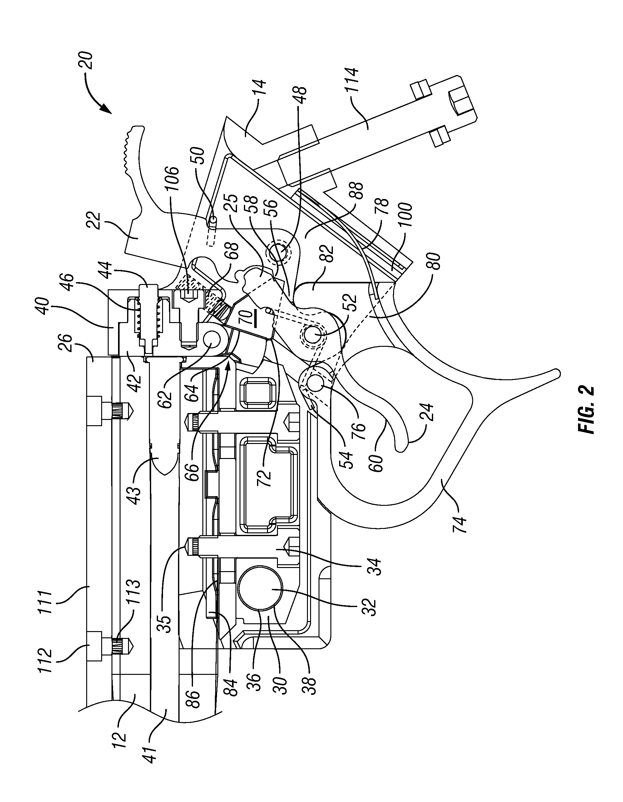
[0023]Referring to FIG. 2, the barrel 12 is connected to the receiver 14 by way of a barrel tang 30 and a pivot pin 32, located near the barrel breech end 26. The barrel tang 30 is attached to the barrel 12 by bolts 34 threaded into holes 35 tapped into the outer surface of the barrel 12. The barrel tang 30 includes a transverse through hole 36, while the receiver 14 includes transverse holes 38. The pivot pin 32 is inserted through the transverse holes 36, 38 to pivotally mount the barrel 12 to the receiver 14. The barrel 12 is pivotal between a closed position, where the breech end 26 rests against a breech portion 40 of ...


PUM


Abstract

A single-shot break action firearm includes a receiver, a barrel, and a stock. The receiver has a breach portion that defines a cavity that is sized and shaped to house a breechblock therein. The breechblock is constructed from a powdered metal formed by metal-injection-molding. The breechblock is form from a higher strength material than the receiver to contain explosive forces produced during discharge of the firearm. The barrel is connected with the receiver and extends forward therefrom. The stock is connected with the receiver and extends rearward therefrom.

Description

CROSS REFERENCE TO RELATED APPLICATION[0001]room This application claims the benefit of U.S. Provisional Application No. 61 / 367,950, filed Jul. 27, 2010, entitled “UNITARY BREECH BLOCK ASSEMBLY”, the aforementioned application being hereby incorporated by reference in its entirety.FIELD OF THE INVENTION[0002]The present invention relates to firearms and, more particularly, to single-shot break action firearms.BACKGROUND OF THE INVENTION[0003]Single-shot break action firearms, typically, have a barrel enclosing a bore that extends from a breech end to a muzzle end of the barrel. The barrel is pivotally mounted to a receiver disposed near the breech end of the barrel. The receiver includes a breechblock, which blocks the breech end of the barrel when the barrel is in a closed position. Pivoting motion of the barrel on the receiver shifts the barrel to an open position wherein the breechblock does not block the breech end of the barrel. The breechblock typically houses a firing pin, wh...

Claims


Application Information

Patent Timeline
IPC IPC(8): F41A3/58
CPCF41A3/58
Inventor LANEY, MARK C.
Owner SMITH & WESSON
Why Eureka
Try Eureka