Combined probe head for a vertical probe card and method for assembling and aligning the combined probe head thereof

a combined probe and probe head technology, applied in the field of combined probe heads, can solve the problems of increasing repair costs, easy wear and abrasion of the probe head b>4/b>, and easy generation of wear and abrasion of the probe head, so as to avoid mutual interference and accurate alignment of the sub-probe head

Active Publication Date: 2012-02-02
MICROELECTRONICS TECH INC
View PDF34 Cites 26 Cited by
  • Summary
  • Abstract
  • Description
  • Claims
  • Application Information

AI Technical Summary

Benefits of technology

[0008]According to another embodiment of the present invention, a method for assembling and aligning a combined probe head is provided. In the method for assembling and aligning the first combined probe head, the combined probe head may include a locating plate and a plurality of sub-probe head, in which there are a plurality of probes inserted between the upper sub-die and the lower sub-die of each sub-probe head. After the sub-probe heads are assembled and fixed in the locating plate, an accurate alignment of each sub-probe head is achieved by using a probe alignment unit in order to position the proper locating distribution of all of the respective probes, and the positioned sub-probe heads are assembled and fixed in the locating plate.
[0009]Therefore, by adopting the embodiments of the present invention, the layout areas of a vertical probe card can be differentiated or segmented in order to avoid mutual interference under or during repair process.

Problems solved by technology

After frequent test operations have been performed on the vertical probe card 1, the probes 5 disposed in the probe head 4 may easily generate wear and abrasions of varying degrees.
As a result, there-insertions of other replacement probes 5 are required, which may increase repair cost and thereby waste maintenance time and labor, especially probe cards having high pin count will be affected more seriously.

Method used


Image

  • Combined probe head for a vertical probe card and method for assembling and aligning the combined probe head thereof
  • Combined probe head for a vertical probe card and method for assembling and aligning the combined probe head thereof
  • Combined probe head for a vertical probe card and method for assembling and aligning the combined probe head thereof

Examples


embodiment 1

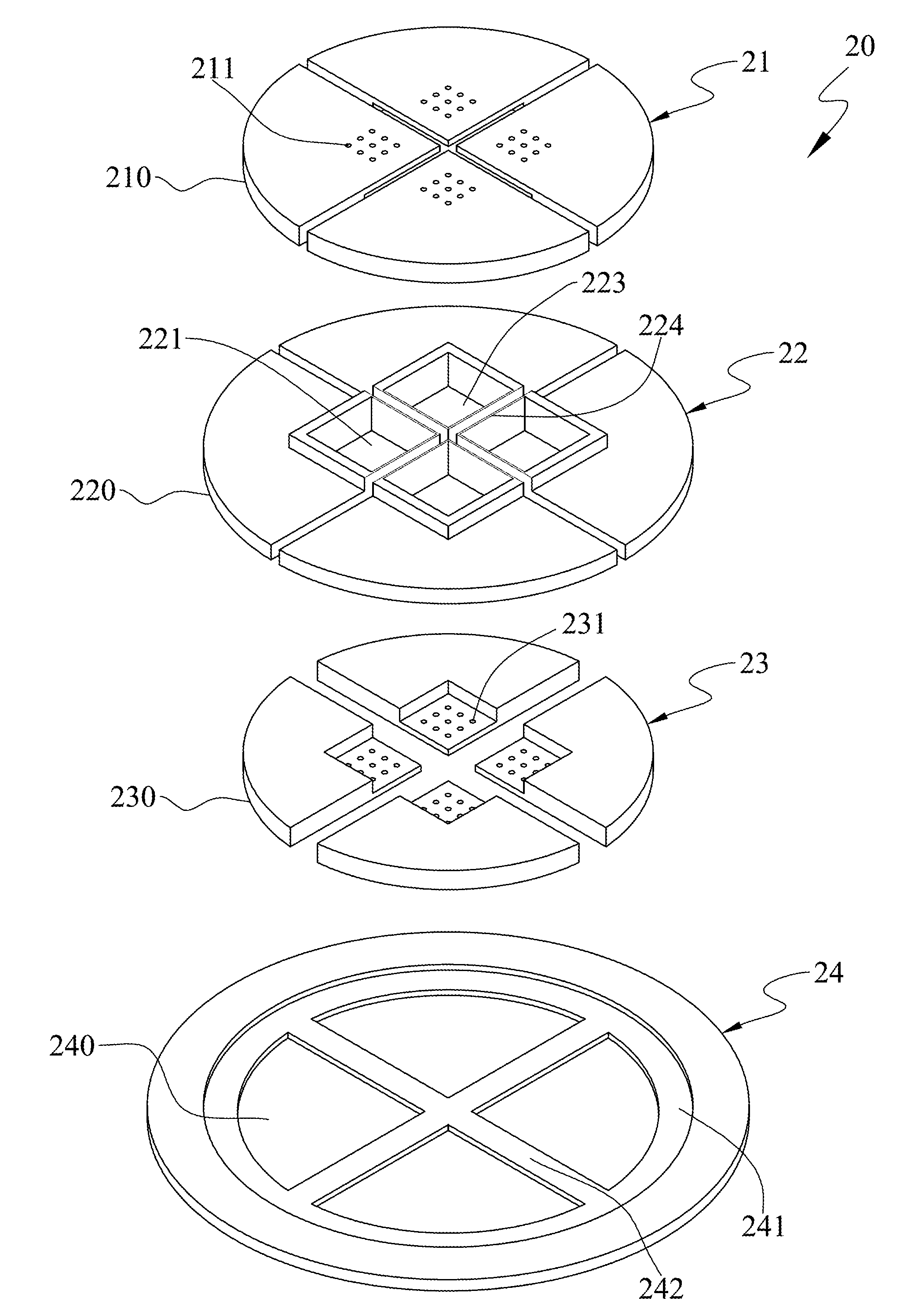
[0022]In this embodiment, a combined probe head 20 having three dies is provided. Please refer to FIG. 2-1. As shown, the combined probe head 20 may include an upper die (UD) 21, a middle die (MD) 22, a lower die (LD) 23, and a locating plate 24. The upper die 21, the middle die 22, and the lower die 23 include a plurality of upper sub-dies 210, a plurality of middle sub-dies 220, and a plurality of lower sub-dies 230, respectively. Be noted that a total number of the upper sub-dies 210 of the upper die 21, a total number of the middle sub-dies 220 of the middle die 22, and a total number of the lower sub-dies 230 of the lower die 23 are equal to each other, and the positions of the upper sub-dies 210, the middle sub-dies 220, and the lower sub-dies 230 are configured up and down respectively corresponding to each other. However, the total number of the upper sub-dies 210, the middle sub-dies 220, and the lower sub-dies 230 are not limited to any particular number, which is to be co...

embodiment 2

[0027]In Embodiment 2, a combined probe head 30 having two dies is provided. FIG. 4-1 is a 3D exploded view of the combined probe head 30 and FIG. 4-2 is an assembly cross-sectional view of the combined probe head 30. This embodiment can be applied to a vertical probe card with multi-DUT. The combined probe head 30 may include an upper die 31, a lower die 32, and a locating plate 33. The upper die 31 and the lower die 32 include a plurality of upper sub-dies 310 and a plurality of lower sub-dies 320, respectively. Be noted that a total number of the upper sub-dies 310 of the upper die 31 and a total number of the lower sub-dies 320 of the lower die 32 are equal to each other (as shown in FIG. 4-1, the total number is equal to two), and the positions of the upper sub-dies 310 and the lower sub-dies 320 are arranged up and down corresponding to each other. Besides, there are a plurality of corresponding holes 311, 321 disposed on the upper sub-dies 310 and the lower sub-dies 320, resp...

embodiment 3

[0033]In the Embodiment 3, another combined probe head 40 is provided, which can be applied to a vertical probe card with high pin count and / or multi-DUT. Please refer to the assembly structural view shown in FIG. 5-1. The combined probe head 40 may include an upper die 41, a lower die 42, and a locating plate 43. The upper die 41 includes a plurality of upper sub-dies 410 (such as, the three upper-sub-dies 410 shown in FIG. 5-1), wherein the upper sub-dies 410 are in horizontal alignment with each other, and there are a plurality of holes 411 disposed on each of the upper sub-dies 410. The lower die 42 includes a plurality of layout areas 420 of the probes, wherein there is a plurality of holes 421 disposed on each of the layout areas 420. Therefore, each upper sub-die 410 can correspond to one of the layout areas 420 to be disposed on the lower die 42, such that a plurality of probes 44 can be inserted between the upper sub-dies 410 and the layout areas 420 of the lower die 42. Th...


PUM


Abstract

A combined probe head being disposed in a space transformer of a vertical probe card is provided, in which the combined probe head is used for differentiating or segmenting a layout area of the probes in the vertical probe card. The combined probe head may include a locating plate and sub-probe heads. The locating plate may include fixed portions. Each sub-probe head may include corresponding sub-dies and probes inserted between the sub-dies, and each sub-probe head is assembled and fixed in the corresponding fixed portion. Therefore, the layout area of the probes in the vertical probe card can be respectively differentiated or segmented from the sub-probe heads in order to avoid mutual interference under repair process. In addition, a related method for assembling and aligning the above mentioned combined probe head is provided.

Description

FIELD OF THE INVENTION[0001]The present invention relates to a combined probe head and a related method for assembling and aligning the combined probe head, and more particularly, to a combined probe head for a vertical probe card and method for assembling and aligning the combined probe head.BACKGROUND OF THE INVENTION[0002]During a wafer test, a probe card is usually used in a testing equipment for contacting the device under test (DUT) and transferring testing signals in order to obtain electrical properties of the DUT. The probe cards can be classified into a cantilever probe card (CPC) and a vertical probe card (VPC).[0003]FIG. 1-1 and FIG. 1-2 are structural illustrative drawings of a conventional vertical probe card 1 according to the known art. The conventional vertical probe card 1 includes a printed circuit board 2, a space converting layer 3 disposed in one side of the printed circuit board 2, a probe head 4 disposed in one side of the space converting layer 3, and a plur...

Claims


Application Information

Patent Timeline
Patent Type & Authority Applications(United States)
IPC IPC(8): G01R1/067
CPCG01R1/07342G01R31/2889G01R3/00G01R1/07357G01R1/07371
Inventor HUANG, CHAO-CHINGCHEN, WEN-CHICHANG, CHIU-CHU
Owner MICROELECTRONICS TECH INC
Why Eureka
Try Eureka