Driving circuit of light emitting diode, decoding circuit and decoding method thereof

Inactive Publication Date: 2012-02-02
MY SEMI
View PDF4 Cites 10 Cited by
  • Summary
  • Abstract
  • Description
  • Claims
  • Application Information

AI Technical Summary

Benefits of technology

[0015]In summary, the driving circuit of light emitting diode, decoding circuit and decoding method thereof according to the present invention enable internal detections on the frequency of the clock signal, thereby spontaneously adjusting the sampling frequency based on the detected oscillation frequency in order to correctly sample the DMX512 data s

Problems solved by technology

In fact, before the introduction of the DMX512 protocol, several light control protocols had been developed for the lighting devices; however, as the lighting devices/systems become more and more complicated, the conventional protocols may not offer the most suitable solutions, prompting the introduction of the DMX512 protocol.
Howev

Method used


Image

  • Driving circuit of light emitting diode, decoding circuit and decoding method thereof
  • Driving circuit of light emitting diode, decoding circuit and decoding method thereof
  • Driving circuit of light emitting diode, decoding circuit and decoding method thereof

Examples


first embodiment

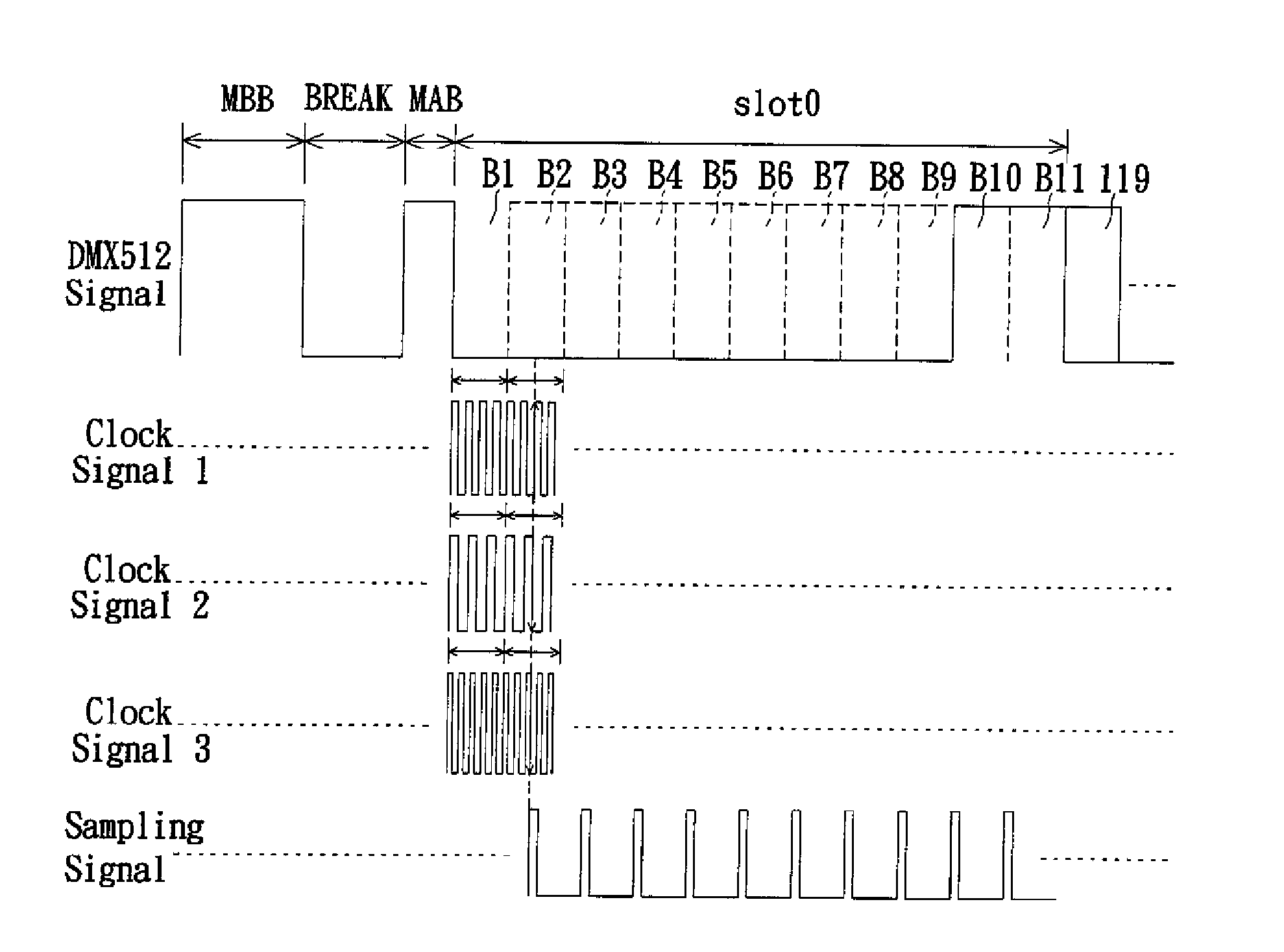
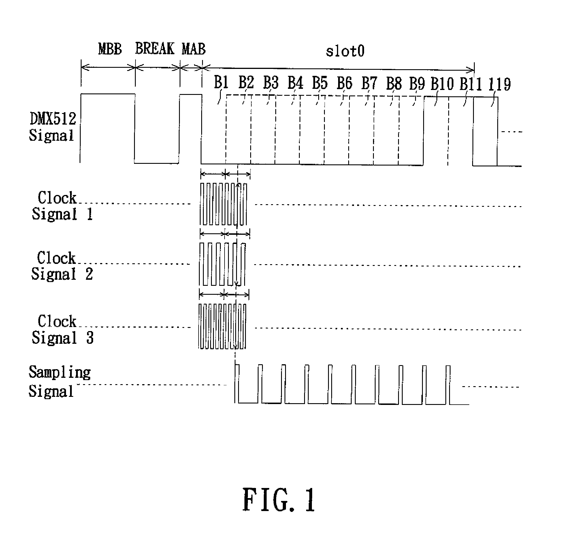
[0020]Refer to FIG. 1, wherein a diagram of the frequency estimation for a clock signal according to a first embodiment of the present invention is shown. The DMX512 signal includes a break (“BREAK”), a “Mark time after BREAK” (MAB), a start code (located at the first slot (slot0)), channel data (located among the second slot (slot1) to the 513th slot (slot512). In one implementation, the slots from the second slot (slot1) to the 513th slot (slot512) follow the first slot (slot0), which is not shown in FIG. 1. A “Mark time between slots” 119 and a “Mark time before BREAK” (MBB). BREAK indicates the start of a DMX512 data packet, which is a low-level output of 88 microseconds, and is followed by MAB, which is a high-level output of 8 microseconds or two 4-microsecond high-level pulses. The start code (SC) represents the start for the data flow, which has the same format as the channel data and usually includes 11 bits or lasts for 44 microseconds. In the DMX512 protocol, the standard...

second embodiment

[0031]Refer now to FIG. 3, wherein a flowchart of the decoding method according to a second embodiment of the present invention is shown. The present decoding method is applicable to decoding a data signal in compliance with the DMX512 protocol. The decoding method includes receiving a clock signal and a data signal, wherein the data signal includes a plurality of slots and each slot is associated with a time period as shown in FIG. 1 (STEP S310), sampling one of the slots based on the clock signal to generate a sample number corresponding to the slot sampled (STEP S320), outputting a reference signal corresponding to the frequency of the clock signal according to the sample number (STEP S330), and sampling the data signal according to the clock signal and the reference signal in order to decode the data carried by the data signal (STEP S340). With descriptions for the aforementioned embodiment, other implementation details of the present decoding method may be deduced by those skil...


PUM


Abstract

A driving circuit, a decoding circuit and a decoding method thereof are provided. The decoding circuit includes an oscillator and a decoder including a frequency determining unit and a decoding unit. The frequency determining unit receives a clock signal and a data signal which is corresponding to DMX512 protocol, and samples one slot of the data signal according to the clock signal to generate a sample number corresponding to a slot period of the slot. Then, the frequency determining unit outputs a reference signal corresponding to the frequency of the clock signal according to the sample number. The decoding unit samples the data signal according to the clock signal and the reference signal to decode data carried on the data signal. The decoding circuit is able to sample the data signal correctly without disposing any external frequency adjusting element.

Description

BACKGROUND OF THE INVENTION[0001]1. Field of the Invention[0002]The present invention relates to a DMX512 decoding circuit, and more particularly, to a driving circuit of light emitting diode (LED), decoding circuit and decoding method thereof.[0003]2. Description of Related Art[0004]DMX512 indicates a standard for digital communication interface which is largely used as a communication protocol between lighting devices and comprises the data format for data transmissions, the electrical feature of devices and the connector type. The DMX512 protocol was initially developed under the Engineering Commission of United States Institute for Theatre Technology (USITT). In fact, before the introduction of the DMX512 protocol, several light control protocols had been developed for the lighting devices; however, as the lighting devices / systems become more and more complicated, the conventional protocols may not offer the most suitable solutions, prompting the introduction of the DMX512 proto...

Claims


Application Information

Patent Timeline
IPC IPC(8): H03M7/00H05B37/02
CPCH05B37/0272H05B33/0845H05B47/19H05B45/305
Inventor LIN, CHUN-FUKUO, CHUN-TINGHSIEH, CHENG-HAN
Owner MY SEMI
Why Eureka
Try Eureka