Method for confirming memory controller clock calibration value and system thereof

A memory controller and clock calibration technology, applied in the direction of generating/distributing signals, etc., can solve the problems of increasing the user's operating burden and slow speed

Inactive Publication Date: 2009-06-03
ARTEK MICROELECTRONICS
View PDF0 Cites 18 Cited by
  • Summary
  • Abstract
  • Description
  • Claims
  • Application Information

AI Technical Summary

Problems solved by technology

This method of determining the calibration value requires human participation, increases the us

Method used


Image

  • Method for confirming memory controller clock calibration value and system thereof
  • Method for confirming memory controller clock calibration value and system thereof
  • Method for confirming memory controller clock calibration value and system thereof

Examples


Embodiment Construction

[0037] In order to make the objects and advantages of the present invention clearer, the present invention will be further described in detail below in conjunction with the accompanying drawings and embodiments.

[0038] First, the system of the present invention for determining a memory controller clock calibration value is described.

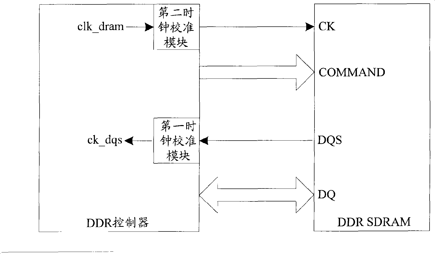
[0039] Image 6It is a schematic structural diagram of a system for determining a clock calibration value of a memory controller in an embodiment of the present invention. In this embodiment, the memory controller can control the DDR memory and the SDR memory compatible. Combine below Image 6 , respectively explain the functions of each device in the system and the connection relationship between them.

[0040] 1) The first clock calibration device.

[0041] The first clock calibration device is used for calibrating the clock signal used for data sampling output by the selection device according to the first calibration value output by the...


PUM


Abstract

The invention discloses a system for confirming a memory controller clock calibration value. The system consists of an appointing device, a read-write device, a comparing device and a confirming device which are coordinated with each other. A first clock calibrating device is appointed with a first calibration value, and the first clock calibrating device is used for reading preset detection data which is written in a memory according to a calibrated clock signal output by the appointed first calibration value. Whether the clock signal calibrated according to the appointed first calibration value can ensure correct data sampling is judged by comparing whether the read detection data is consistent with the preset detection data. The process is repeated continuously, a first calibration value range which ensures the correct data sampling can be obtained, and any first calibration value can be taken from the range to be used as a finial calibration value of the first clock calibrating device. The invention also discloses a method for confirming the memory controller clock calibration value. The invention can confirm the clock calibration value ensuring the accurate data sampling independently and confirms fast.

Description

technical field [0001] The invention relates to clock calibration technology, in particular to a method and system for determining a memory controller clock calibration value. Background technique [0002] Double data rate synchronous dynamic random access memory (DDR SDRAM, Double Data Rate Synchronous Dynamic Random Access Memory) (hereinafter referred to as DDR memory) and single data rate synchronous dynamic random access memory (SDR SDRAM, Single Data Rate Synchronous Dynamic Random Access Memory) (hereinafter referred to as SDR memory) ) are commonly used storage media, the DDR controller can be used to access the DDR memory to implement data writing and reading, and the SDR controller can be used to access the SDR memory to implement data writing and reading. [0003] figure 1 It is a schematic diagram of the interface connection between the DDR controller and the DDR memory. The first clock calibration device in the DDR controller calibrates the DQS signal sent by ...

Claims


Application Information

Patent Timeline
IPC IPC(8): G06F1/04
Inventor 王宏斌
Owner ARTEK MICROELECTRONICS
Why Eureka
Try Eureka