Transitioning Between Different Views of a Diagram of a System

Inactive Publication Date: 2012-02-02
NATIONAL INSTRUMENTS
View PDF14 Cites 17 Cited by
  • Summary
  • Abstract
  • Description
  • Claims
  • Application Information

AI Technical Summary

Benefits of technology

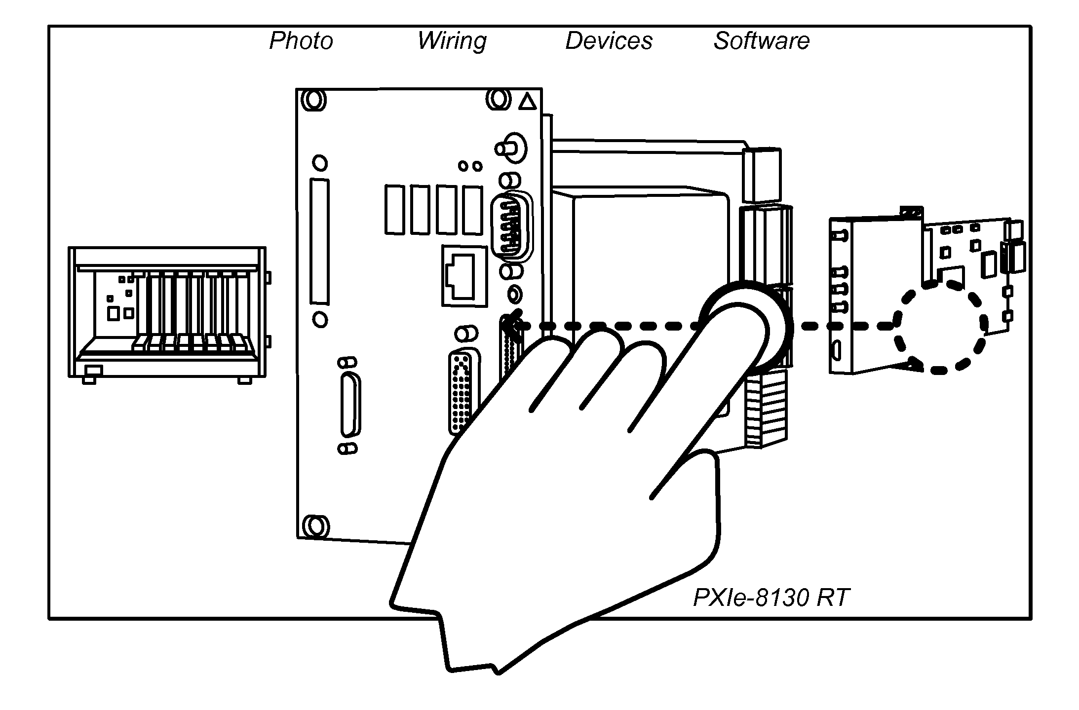
[0008]The first view and the second view may vary according to levels of abstraction. For example, the first view may correspond to a first level of abstraction of the first portion of the system and the second view may correspond to a second level of abstraction of the first portion of the system. In some embodiments, the first level may be a higher level than the second level. For example, as the user provides the first gesture the level of abstraction may increase or decrease. In contrast, another gesture may allow the user to view levels of abst

Problems solved by technology

Accordingly, it is difficult for a designer or user of a system to fully understand all of hardware, ph

Method used


Image

  • Transitioning Between Different Views of a Diagram of a System
  • Transitioning Between Different Views of a Diagram of a System
  • Transitioning Between Different Views of a Diagram of a System

Examples


Example

[0025]While the invention is susceptible to various modifications and alternative forms, specific embodiments thereof are shown by way of example in the drawings and are herein described in detail. It should be understood, however, that the drawings and detailed description thereto are not intended to limit the invention to the particular form disclosed, but on the contrary, the intention is to cover all modifications, equivalents and alternatives falling within the spirit and scope of the present invention as defined by the appended claims.

DETAILED DESCRIPTION OF THE INVENTION

Incorporation by Reference

[0026]The following references are hereby incorporated by reference in their entirety as though fully and completely set forth herein:[0027]U.S. Pat. No. 4,914,568 titled “Graphical System for Modeling a Process and Associated Method,” issued on Apr. 3, 1990.[0028]U.S. Pat. No. 5,481,741 titled “Method and Apparatus for Providing Attribute Nodes in a Graphical Data Flow Environment”.[...


PUM


Abstract

Presenting different views of a system based on input from a user. A first view of a first portion of the system may be displayed. For example, the first portion may be a device of the system. User input specifying a first gesture may be received. In response to the first gesture, a second view of the first portion of the system may be displayed. For example, the first view may represent a first level of abstraction of the portion of the system and the second view may represent a second level of abstraction of the portion of the system. A second gesture may be used to view a view of a different portion of the system. Additionally, when changing from a first view to a second view, the first view may “morph” into the second view.

Description

PRIORITY INFORMATION[0001]This application is a continuation-in-part of U.S. application Ser. No. 12 / 869,270, titled “Graphically Specifying and Indicating Targeted Execution in a Graphical Program”, filed Aug. 26, 2010, whose inventors were Jeffrey L. Kodosky, David W. Fuller III, Timothy J. Hayles, Jeffrey N. Correll, John R. Breyer, Jacob Kornerup, Darshan K. Shah, and Aljosa Vrancic, which is a continuation-in-part of U.S. application Ser. No. 11 / 776,196, titled “Diagram That Visually Indicates Targeted Execution”, filed Jul. 11, 2007, whose inventors were Jeffrey L. Kodosky, David W. Fuller III, Timothy J. Hayles, Jeffrey N. Correll, John R. Breyer, Jacob Kornerup, Darshan K. Shah, and Aljosa Vrancic, which claims benefit of priority of the following provisional applications: U.S. provisional application Ser. No. 60 / 942,834 titled “Diagram That Visually Indicates Targeted Execution” filed Jun. 8, 2007, whose inventors were Jeffrey L. Kodosky, David W Fuller III, Timothy J. Hayl...

Claims


Application Information

Patent Timeline
IPC IPC(8): G06T13/00G09G5/00
CPCG05B19/0426G05B2219/23248G05B2219/23258G06F17/5054G06F3/04883G06F8/34G05B2219/23273G06F30/34
Inventor GABBERT, ADAM K.KODOSKY, JEFFREY L.FULLER, III, DAVID W.HAYLES, TIMOTHY J.CORRELL, JEFFREY N.BREYER, JOHN R.KORNERUP, JACOBSHAH, DARSHAN K.VRANCIC, ALJOSA
Owner NATIONAL INSTRUMENTS
Why Eureka
Try Eureka