Pressure adjustor and method of manufacturing the same, speaker device using the pressure adjustor, electronic device, and vehicle

Inactive Publication Date: 2012-02-02
PANASONIC CORP
View PDF15 Cites 29 Cited by
  • Summary
  • Abstract
  • Description
  • Claims
  • Application Information

AI Technical Summary

Benefits of technology

[0022]With this configuration, it is possible to improve the

Problems solved by technology

However, if a speaker cabinet of the speaker device is made small, it is difficult to reproduce bass due to the influence of the acoustic stiffness that the spea

Method used


Image

  • Pressure adjustor and method of manufacturing the same, speaker device using the pressure adjustor, electronic device, and vehicle
  • Pressure adjustor and method of manufacturing the same, speaker device using the pressure adjustor, electronic device, and vehicle
  • Pressure adjustor and method of manufacturing the same, speaker device using the pressure adjustor, electronic device, and vehicle

Examples


embodiment 1

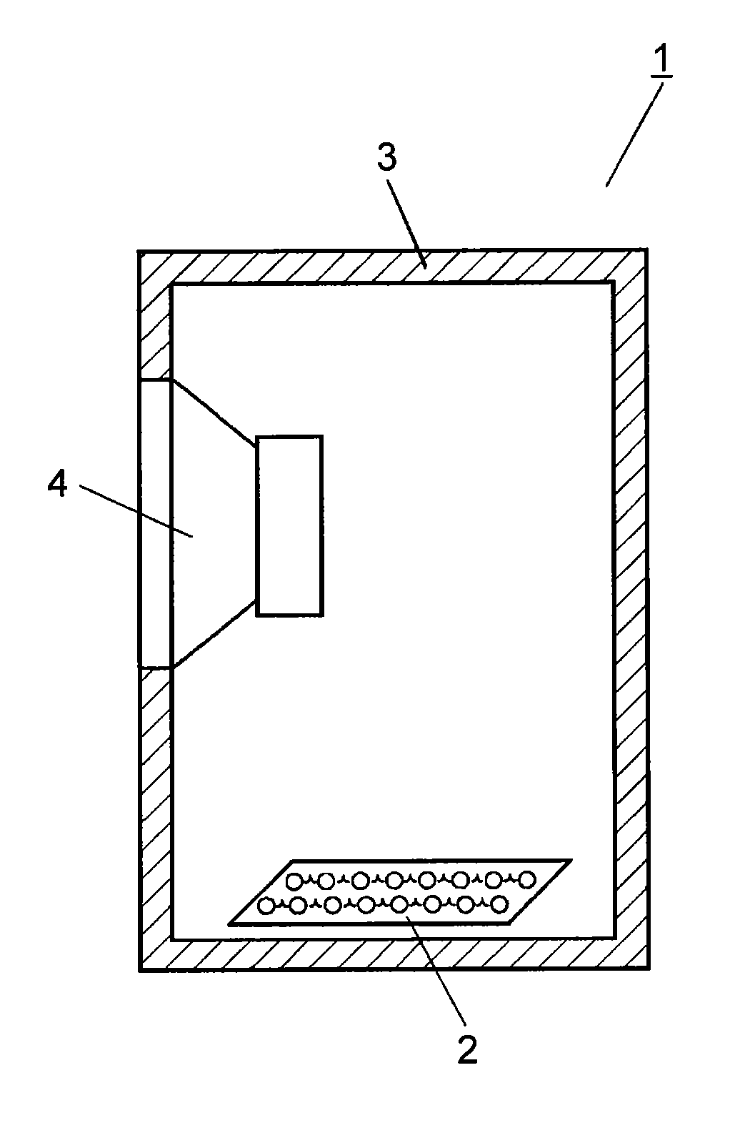
[0031]Hereinafter, the configuration of an activated carbon sheet which is a pressure adjustor and a speaker device of Embodiment 1 will be described with reference to FIGS. 1 and 2.

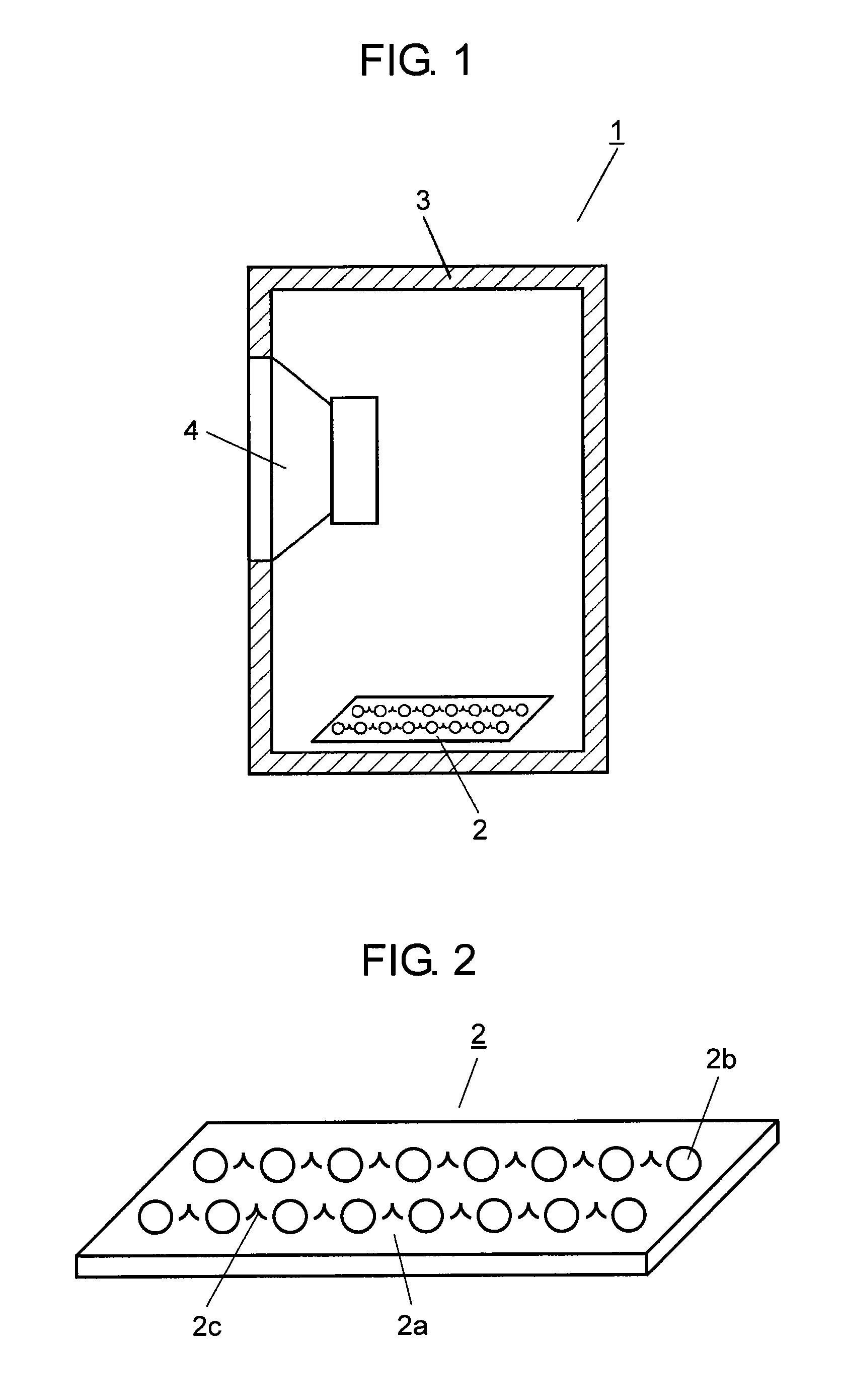
[0032]FIG. 1 is a view illustrating a speaker device according to Embodiment 1 of the invention. FIG. 2 is a schematic view of an activated carbon sheet according to Embodiment 1 of the invention.

[0033]As shown in FIG. 1, speaker device 1 has a configuration in which activated carbon sheet 2 is disposed inside cabinet 3, and speaker unit 4 is provided in cabinet 3. In Embodiment 1, in the configuration shown in FIG. 1, activated carbon sheet 2 is disposed in the bottom surface portion of cabinet 3; however, for example, a configuration may be used in which activated carbon sheet 2 is disposed in the lateral or top surface of cabinet 3.

[0034]As shown in FIG. 2, activated carbon sheet 2 is formed in a manner in which particle-like activated carbon powder 2b and binder 2c are attached to supporter 2a that c...

example 1-1

[0058]The coconut husk was carbonized and then activated with vapor to produce powdered activated carbon powder 2b. 95% by weight of this activated carbon powder 2b having average particle diameter D50 of about 20 μm and the volume of pores having a radius of 1 nm or less per unit weight of 0.6 ml / g was mixed with 3% by weight of an ammonium salt of CMC which is an aqueous binder as binder 2c and 2% by weight of a latex of a styrene butadiene rubber which is an aqueous binder dispersion, thereby producing activated carbon sheet 2. Produced activated carbon sheet 2 containing 1 g of activated carbon powder 2b was introduced into a 30 cc glass tube syringe 13, and differential pressure generated when the volume of 30 cc glass tube syringe 13 was compressed to 5 cc from 30 cc was measured.

example 1-2

[0059]The coconut husk was carbonized and then activated with vapor to produce powdered activated carbon powder 2b. 76% by weight of this activated carbon powder 2b having average particle diameter D50 of about 20 μm and the volume of pores having a radius of 1 nm or less per unit weight of 0.6 ml / g was mixed with 12% by weight of an ammonium salt of CMC which is an aqueous binder as binder 2c and 12% by weight of a latex of a styrene butadiene rubber which is an aqueous binder dispersion, thereby producing activated carbon sheet 2. Produced activated carbon sheet 2 containing 1 g of activated carbon powder 2b was introduced into a 30 cc glass tube syringe 13, and differential pressure generated when the volume of 30 cc glass tube syringe 13 was compressed to 5 cc from 30 cc was measured.


PUM

PropertyMeasurementUnit
Timeaaaaaaaaaa
Percent by massaaaaaaaaaa

Abstract

A pressure adjustor includes a sheet-like supporter formed of unwoven fabric or woven fabric, a plurality of activated carbon powder particles attached to the supporter, and binders binding the plurality of activated carbon powder particles to each other. If this pressure adjustor is disposed inside a cabinet of a speaker device including a speaker unit provided in the cabinet, a speaker device is obtained which has an excellent bass reproduction effect even if the device is made small.

Description

[0001]This application is a U.S. National Phase Application of PCT International Application PCT / JP2010 / 001072.TECHNICAL FIELD[0002]The present invention relates to a pressure adjustor, a speaker device which uses the pressure adjustor and is used for various types of acoustic devices and information communication devices, an electronic device, and a vehicle. More specifically, the invention relates to a speaker device which realizes bass reproduction with a small speaker cabinet by means of the pressure adjustor, and to a method of manufacturing the pressure adjustor.BACKGROUND ART[0003]The recent market trend of the audio industry requires high quality reproduction in response to the prevalence of digital audio devices represented by DVD.[0004]Meanwhile, in terms of the environment around houses and vehicles, there is a strong demand to save space and energy.[0005]As a speaker device that can satisfy the above demand, a speaker device which is small and excellent in deep-bass repr...

Claims


Application Information

Patent Timeline
IPC IPC(8): H04R1/02B23P11/00F16L55/04
CPCH04R2499/13H04R2499/11H04R1/2803Y10T29/49826
Inventor IMAMURA, KEISUKESHIMASAKI, YUKIHIROOHASHI, KIYOSHIKAJIHARA, YOSHIMICHIJIN, YOHEI
Owner PANASONIC CORP
Why Eureka
Try Eureka