Floating packing ring assembly

Inactive Publication Date: 2012-02-02
GENERAL ELECTRIC CO
View PDF4 Cites 39 Cited by
  • Summary
  • Abstract
  • Description
  • Claims
  • Application Information

AI Technical Summary

Benefits of technology

[0005]A packing ring assembly for use between a rotating and a stationary component in a turbomachine is disclosed, the assembly including an arcuate packing ring casing, an arcuate packing ring segment positioned at least partially within the packing ring casing, and a resistance component configured to allow movement of the packing ring segment in an axial direction, relative to the rotating component, between a first and second position in response to a pressure condition. In one embodiment, the resistance component allows movement when the pressure condition comprises approximately 30% of the turbomachine load. Also disclosed is an altered surface topography of the rotating component to accommodate variable length teeth extending from the packing ring segment, such that when the packing ring segment is in the firs

Problems solved by technology

If this radial clearance between the seal faces of the segments and the opposing seal surfaces of the rotating component becomes too large, less restriction is produced and the sealing action is compromised.
Conversely, if the cle

Method used


Image

  • Floating packing ring assembly
  • Floating packing ring assembly
  • Floating packing ring assembly

Examples


Embodiment Construction

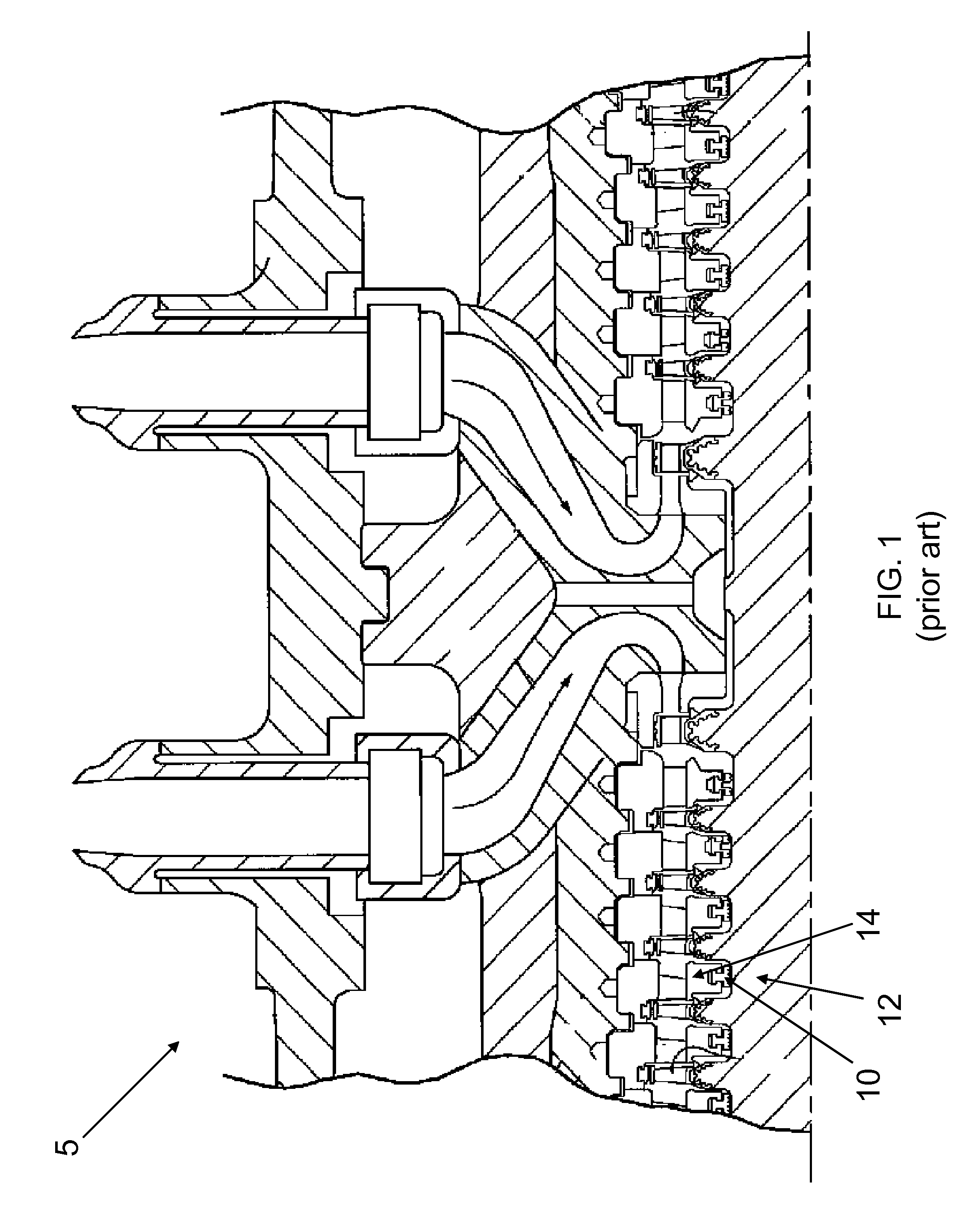
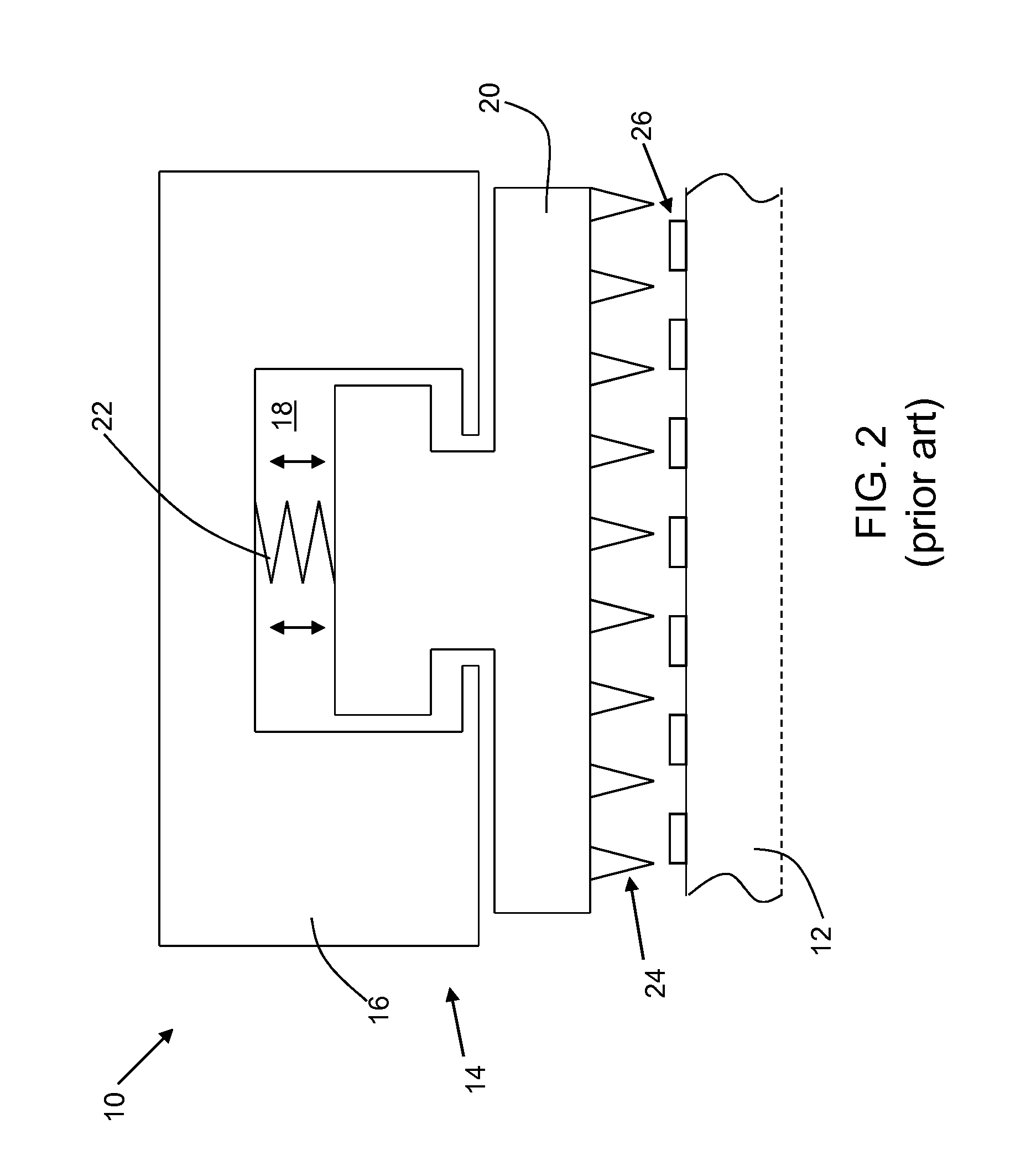
[0014]Turning to FIG. 1, a portion of a turbomachine 5, as known in the art, is shown. Turbomachine 5 includes a plurality of arcuate packing ring assemblies 10 to provide a seal between a rotating component 12 and a stationary component 14. One such packing ring assembly 10, as known in the art, is shown in FIG. 2. Assembly 10, as shown in FIG. 2, includes at least one arcuate packing ring casing 16, at least partially positioned within stationary component 14. Packing ring casing 16 has an annular groove 18. At least one arcuate packing ring segment 20 is also provided, positioned at least partially within annular groove 18. Assembly 10 further includes a spring 22 for moving packing ring segment 20. Spring 22 is positioned within annular groove 18, between packing ring casing 16 and packing ring segment 20, on a side of packing ring segment 20 that is radially opposite rotating component 12. Spring 22 is configured such that it allows packing ring segment 20 to move in a radial d...


PUM


Abstract

A packing ring assembly for use between a rotating and a stationary component in a turbomachine is disclosed, the assembly including an arcuate packing ring casing, an arcuate packing ring segment positioned at least partially within the packing ring casing, and a resistance component configured to allow movement of the packing ring segment in an axial direction, relative to the rotating component, between a first and second position in response to a pressure condition. In one embodiment, the resistance component allows movement when the pressure condition comprises approximately 30% of the turbomachine load. Also disclosed is an altered surface topography of the rotating component to accommodate variable length teeth extending from the packing ring segment, such that when the packing ring segment is in the first position, a clearance between the packing ring segment and the rotating component is larger than when the packing ring segment is in the second position.

Description

BACKGROUND OF THE INVENTION[0001]The disclosure relates generally to rotary turbomachines, and more particularly, to a floating packing ring assembly for use in a turbomachine to avoid transient rubs.[0002]In rotary machines such as turbines, seals are provided between rotating and stationary components. For example, in steam turbines, it is customary to provide a plurality of arcuate packing ring segments to form an annular labyrinth seal between the stationary and rotating components. Typically, the arcuate packing ring segments (typically, four to six per annular seal) are disposed in an annular groove in the stationary component concentric to the axis of rotation of the machine and hence concentric to the sealing surface of the rotating component. Each arcuate seal segment carries an arcuate seal face in opposition to the sealing surface of the rotating component. In labyrinth type seals, the seal faces carry a radially directed array of axially spaced teeth, which teeth are rad...

Claims


Application Information

Patent Timeline
IPC IPC(8): F04D29/04F01D11/08F04D29/08F16J15/44F16J15/46F16J15/447F16J15/16F01D11/02F01D11/00
CPCF01D11/025F16J15/46F16J15/4472F16J15/445
Inventor NATARAJAN, RAJASEKARALAMSETTY, RAKESH VAMSIMEHRA, MAHENDRA SINGHSANCHEZ, NESTOR HERNANDEZSRINIVASAN, MANIKANDAN
Owner GENERAL ELECTRIC CO
Why Eureka
Try Eureka