Card for interconnecting electronic components using insulated cable or wire

a technology of electronic components and wiring cards, applied in the direction of electrically conductive connections, coupling device connections, electrical apparatus, etc., can solve the problems of increasing the time of operation, circuit reading and understanding is difficult, and the operation consumes a lot of time, so as to save measurement

Inactive Publication Date: 2012-02-02
GRUPO CORPORATIVO NOSTRIP S DE R L DE
View PDF0 Cites 37 Cited by
  • Summary
  • Abstract
  • Description
  • Claims
  • Application Information

AI Technical Summary

Benefits of technology

[0014]It is the first intention of present to provide a user with a new connection method of electric, electronic and digital components by providing a new interconnection card of electric and electronic components which terminal legs are inserted into the access boreholes to C-shaped connector clamps or similar but not identical, connector clamps to those in published patent Des. 235,554 (as shown in FIG. 1) each made of conductive material and each in turn a component of conductive lines. Said holes are located on the upper surface over the casing of present invention. This method is characterized by allowing the user to identify the clamp of any type of connector which will receive the component terminal leg so that the user is able to insert fully confident the component when the connector is similar but not identical to that disclosed in published patent Des. 235,554 or otherwise when dealing with a C-shaped connector care should be taken for inserting the component terminal leg located above of the C-shaped connector ratchet mechanism blade and not passing said leg through said ratchet blade as the action of pulling again the component when making that mistake will cause a possible damage in the ratchet mechanism blade on said C-shaped connector. Component terminals are assembled to each other by copper wire or cable bridges inserted in the card as corresponding to each end at a terminal.
[0015]It is another purpose of present invention to provide user with a new connection method at the time of connecting a copper wire or cable end without removing the sheath to a terminal wherein previously made connections made of insulating material are present over the casing surface in this invention. Said connection serves as a support for measuring node voltage or for transmitting a signal or energy to said components. This method is characterized by allowing to said user savings in the task of remover el copper wire or cable sheathing with clamps or with other tooling designed for this task at said end and so allowing to insert and to push into the corresponding connection terminal the copper wire or cable with sheath after pulling in opposite direction to pushing and thus achieving a successful connection between the copper wire or cable end and the corresponding C-shaped connector (as shown in FIG. 2). This method feature is possible because of the guide cavity design in the C-shaped connector housing located in the casing inner part and due to a ratchet mechanism blade in the C-shaped connector itself. These elements create a connector mechanism by recess in the wire bridge.
[0016]It is another purpose of present invention to provide to the user with a new connection method at the time of interconnecting the electric, electronic, node elements formed by a combination thereof or any combination of the three previously assembled over the casing surface made of insulating material in this invention, with copper wire or cable bridges. This method is characterized by allowing to said user savings in the task of removing a copper wire or cable sheathing with clamps or with other tooling designed for this task and so allowing to insert and to push in the corresponding connection terminal the copper wire bridge with the sheath after pulling in opposite direction to pushing and with this achieving a successful connection between the bridges and the C-shaped connectors (as shown in FIG. 3). It is possible with this time savings caused by the fact of having to remove said sheath. This method feature is possible because of the guide cavity design in the C-shaped connector housing located in casing inner part and due to the ratchet mechanism blade in the C-shaped connector itself. These elements form a connector mechanism by a recess in the wire bridge.
[0017]It is another purpose of present invention to provide user with a new connection method at the time of interconnecting the electric, electronic, node elements formed by a combination thereof or any combination of those three, previously assembled over the casing surface made of insulating material in this invention, with copper wire or cable bridges. This method is characterized by allowing to said user savings in the task of measuring the distance between the corresponding connection terminals to each electronic, electric element, node or any combinations of those three, so allowing to insert the copper wire bridge or cable and passing it by pushing said wire starting from an access borehole in the upper surface of the present invention to its bottom surface after pulling the protruding part from the bridge in the bottom part of the card towards the first push used to pass said sheathed wire or cable through the body of the present invention, said operation being repeated twice, one per point at each corresponding element or node terminal (as shown in FIG. 4); This method feature is possible because of the guide cavity design in the C-shaped connector housing in the casing inner part, because of the ratchet mechanism blade and guide borehole in the C-shaped connector and because of the respective guide boreholes in the short-circuiting elements and forming connector lines of multiple C-shaped connectors among them or other type of lines formed by a similar connector as those described in published patent Des. 235,554 with four C-shaped connectors. These elements form a passing guide for bridging wire to save measurement.

Problems solved by technology

This operation consumes time, which shall be multiplied by the number of interconnections which may be multiple and they may further follow intricate paths which should be sectioned, thus increasing the time in this operation because of the sections to be interconnected.
Circuit reading and understanding is difficult when time is intended to be saved by obviating the step of measuring the distance between terminals.
Although this solution for saving time is attractive, it sacrifices presentation in final wiring work making difficult the task of reading the circuit in case that a new Reading is required, thus spending even more time.
Moreover, electronic noise may be generated by using this solution.
Tightening force is not sufficient to ensure that the wire bridge is fixed in its site because of clip design.
This problem may cause a loss of connections between terminals if the wired circuit in the card intends to be transported in backpacks not designed for this purpose.
Because of the handcrafted wiring method, exposed parts caused by excessive removal of the sheath are not ensured to prevent an accidental short-circuit if the circuit is intended to be handled while energized.
In this case, accidental electric discharges to the users may be generated in turn upon touching the circuit surface when energized.
These problems in practice cause economic and time losses, those which may be present from academic environment until research and development of electronic and electric products.

Method used


Image

  • Card for interconnecting electronic components using insulated cable or wire
  • Card for interconnecting electronic components using insulated cable or wire
  • Card for interconnecting electronic components using insulated cable or wire

Examples


Embodiment Construction

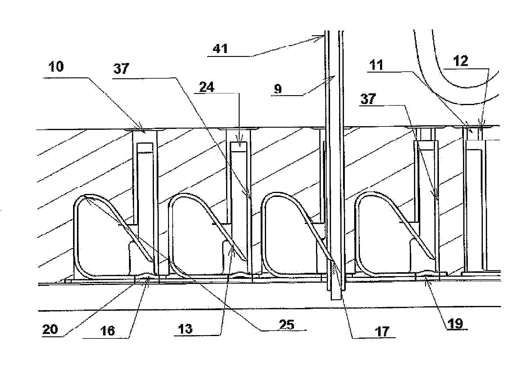
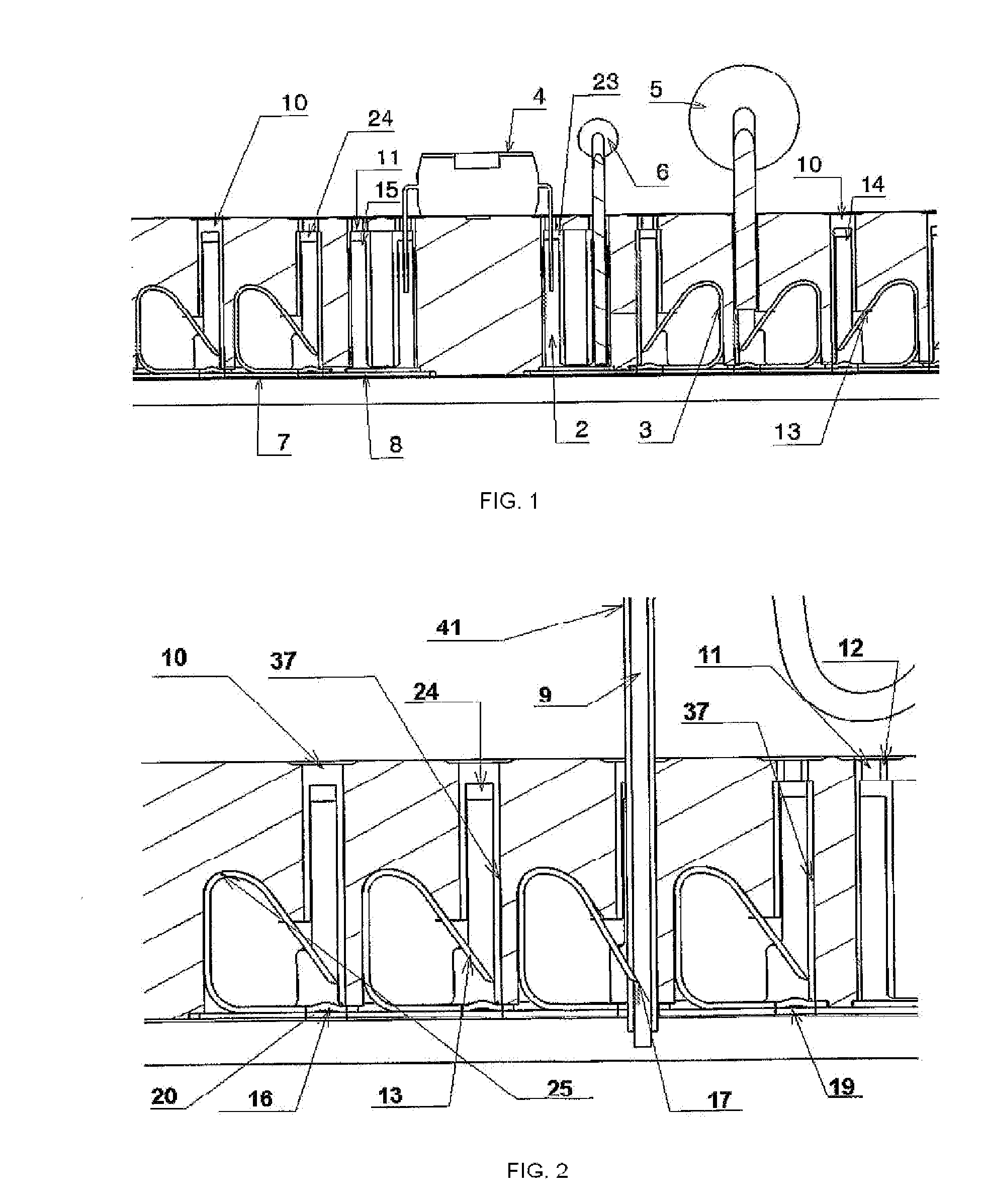
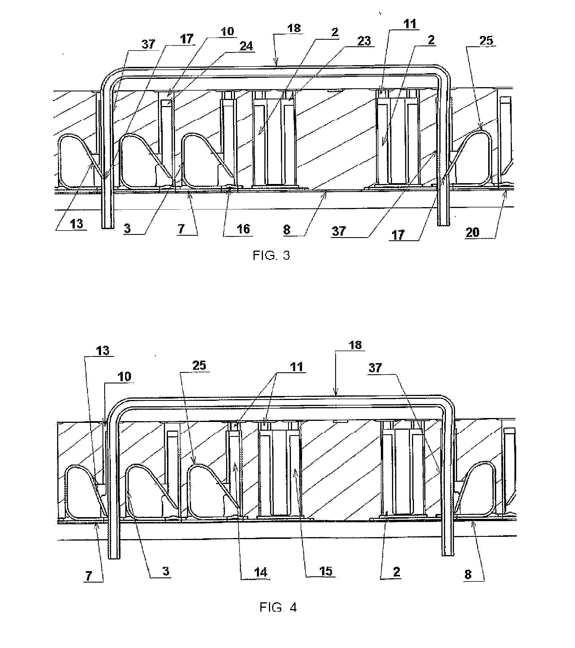
[0060]FIG. 1 shows a cross view of present card with a number of connected components: resistance (6), diode (5), and one IC (4). Said components are inserted by the large size access boreholes (10) and by regular size access boreholes (11) being on casing surface of present card (1). Upon intending an interconnection of electric or electronic components, they are inserted into the C-shaped connectors (14) clamps or in the clamps of similar connectors to those from prior art (15), being opened and in such opening each clamp leg is housed in the opening and housing grooves of the C-shaped connector (24) clamp, and in the opening and housing grooves of a connector clamp similar but not identical to that from prior art (23) in the casing (1), accordingly; this being performed on each side, each leg and each clamp. In said figure the clamp action of a connector to that from prior art (2) is shown and one C-shaped connector (3) which are short-circuited together with another three C-shap...


PUM

PropertyMeasurementUnit
sizeaaaaaaaaaa
sizeaaaaaaaaaa
lengthaaaaaaaaaa

Abstract

A card for interconnecting electronic and electric components using cables or wires with associated sheathing comprises a casing made of insulating material and is provided with holes for accessing cavities which house lines composed of C-shaped connectors which are short-circuited together and lines composed of C-shaped connectors similar to those in the published patent Des. 235,554. Said access holes are arranged in two types of configuration. Lugs are provided at the ends extending along the width of the present card so as to allow the assembly of other cards of the same size which in this case house cylindrical or near-cylindrical objects (commercial pens). The card is insulated at the bottom by an insulating sheath with holes identical to the series of holes in the upper surface of the card. When interconnecting components with sheathed wire or cable a considerable amount of time is saved during wiring.

Description

FIELD OF INVENTION[0001]Present invention refers to an existing fast wiring card known as protoboard, which is a tool with a method of use comprising attaching electric and electronic elements on surface boreholes, thus interconnecting to each other through copper wire or cable bridges to form a circuit. Said method requires measuring the distance between the terminals to be interconnected, adding the penetration distances in the protoboard for cutting the connection wire in order to prevent that wire remainders cause unnecessary noises and said method further requires removing the copper wire sheathing through cutting clamps or other tools. Prior method though effective, requires a significant time and work investment by interconnecting several terminals of a number of elements, as is very common.BACKGROUND OF INVENTION[0002]Products currently used for interconnecting low power electronic and electric components largely resemble the card published in Des. patent 235,554. Electronic...

Claims


Application Information

Patent Timeline
Patent Type & Authority Applications(United States)
IPC IPC(8): H01R4/24H01R43/00H01R12/71
CPCH01R4/4818H01R9/28Y10T29/49117H05K1/0287H05K7/08H01R12/62H01R4/48185
Inventor DEL AGUILA AGUILAR, LUIS RODRIGO
Owner GRUPO CORPORATIVO NOSTRIP S DE R L DE
Why Eureka
Try Eureka